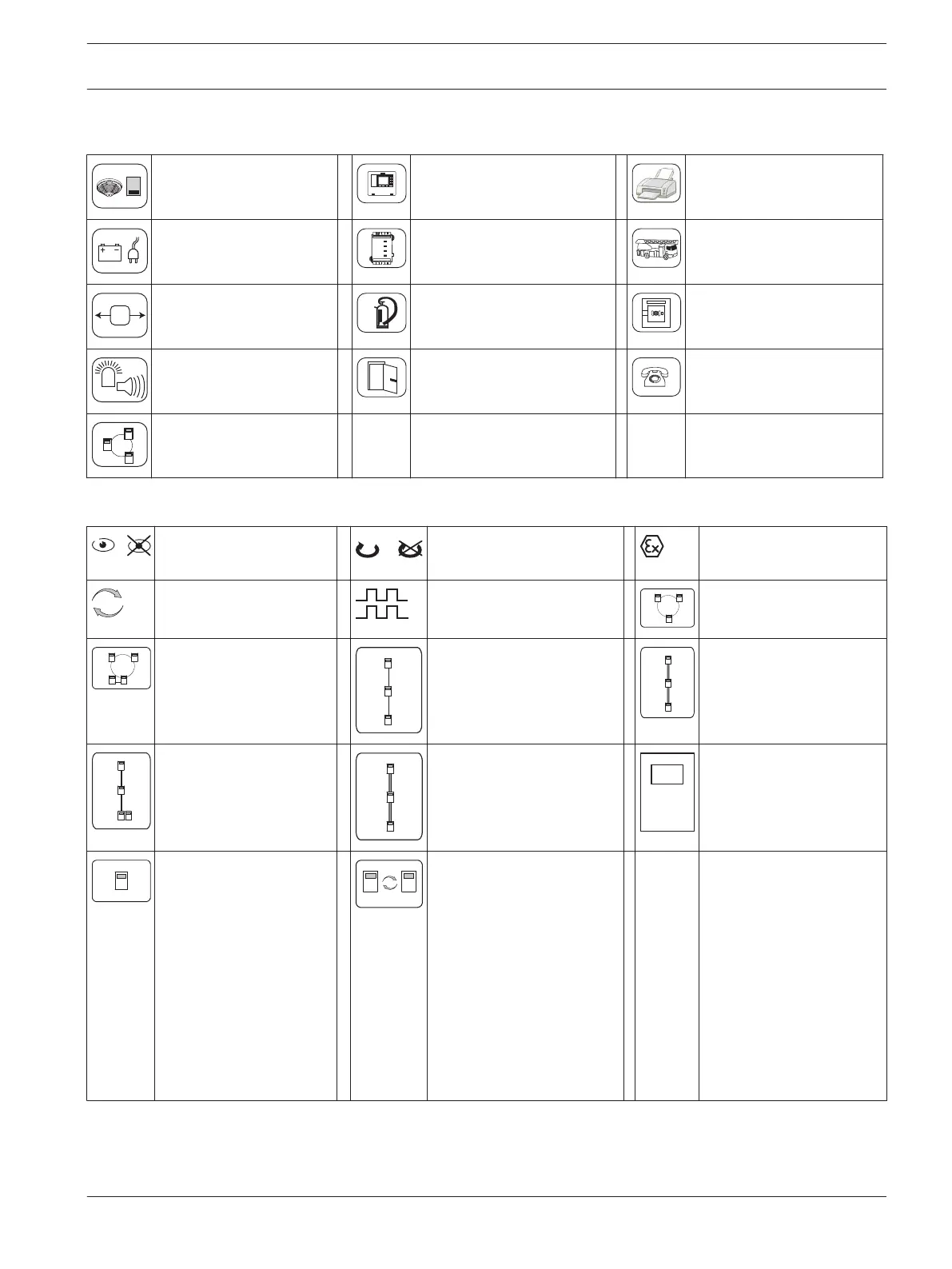
Chapter Symbols
Automatic detectors Operating and display
panels
Printer
Power supply Functional modules Fire service equipment
Interface modules Extinguishing systems Manual call points
Signaling devices Door controls Transmission units
Networking
Connection Symbols
Monitored/ not
monitored
With/without feedback Areas with danger of
explosion
Redundancy Synchronization Loop wiring
Loop wiring with
redundant element
Stub wiring Redundant stub wiring
Stub wiring with
redundant element
Redundant stub wiring
with redundant element
Panel
Standalone panel Standalone panel with
redundancy
EN
54-2,
EN
54-13
etc.
If compliance with this
standard is required,
then use the specified
wiring. You find all
EN54-13 wirings in a
separate section. If the
EN54-13 wiring is
identical to non EN54-13
wiring, then you find the
wiring once in the
EN54-13 chapter.
2.4.1
2.4.2
Modular Fire Panel Notes | en 15
Bosch Sicherheitssysteme GmbH Wiring Guide 2016.07 | 12.6 | F.01U.009.201

 Loading...


