Not allowed For detector bases: The
wiring is valid solely for
the detector base in which
the detector is installed.
- - - - - Optional wiring _______ Mandatory wiring
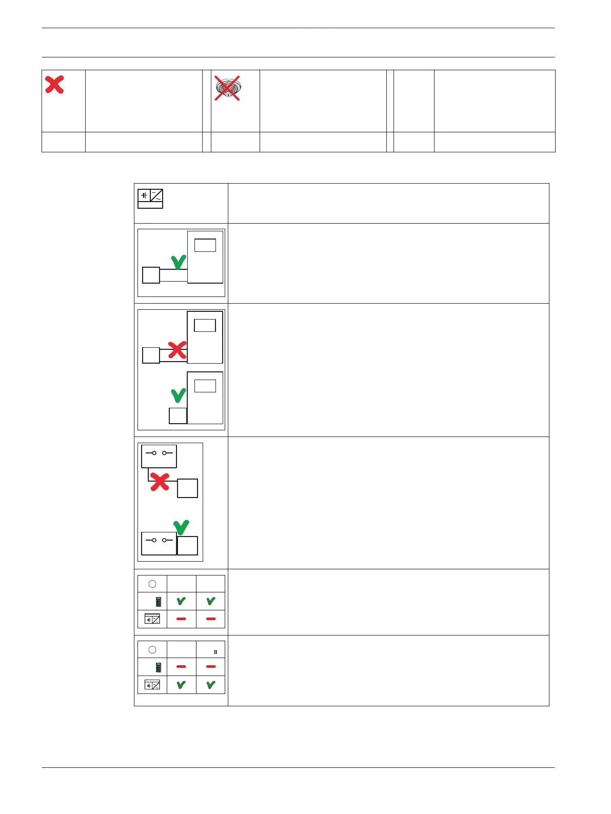
Power Supply and Wiring
Additional power supply
Power supply via the panel
The power supply may be separate from the element.
Power supply via the panel
The element is supplied with power by the panel. The element must
be mounted flush with the panel.
+ -
+ -
AUX
FPP-5000
FPP-5000
External power supply
The element is supplied externally. The external power supply must be
flush with the element.
POWER IN
OUT
POWER IN
OUT
II
AUX
5 - 30 V DC
1
For FLM-420-O8I2:
The power supply to the 2 open collector output groups is provided by
the panel.
POWER IN
OUT
I
POWER IN
OUT
II
AUX
5 - 30 V DC
2
For FLM-420-O8I2:
The power supply to the 2 open collector output groups is provided
externally.
2.4.3
16 en | Notes Modular Fire Panel
2016.07 | 12.6 | F.01U.009.201 Wiring Guide Bosch Sicherheitssysteme GmbH

 Loading...


