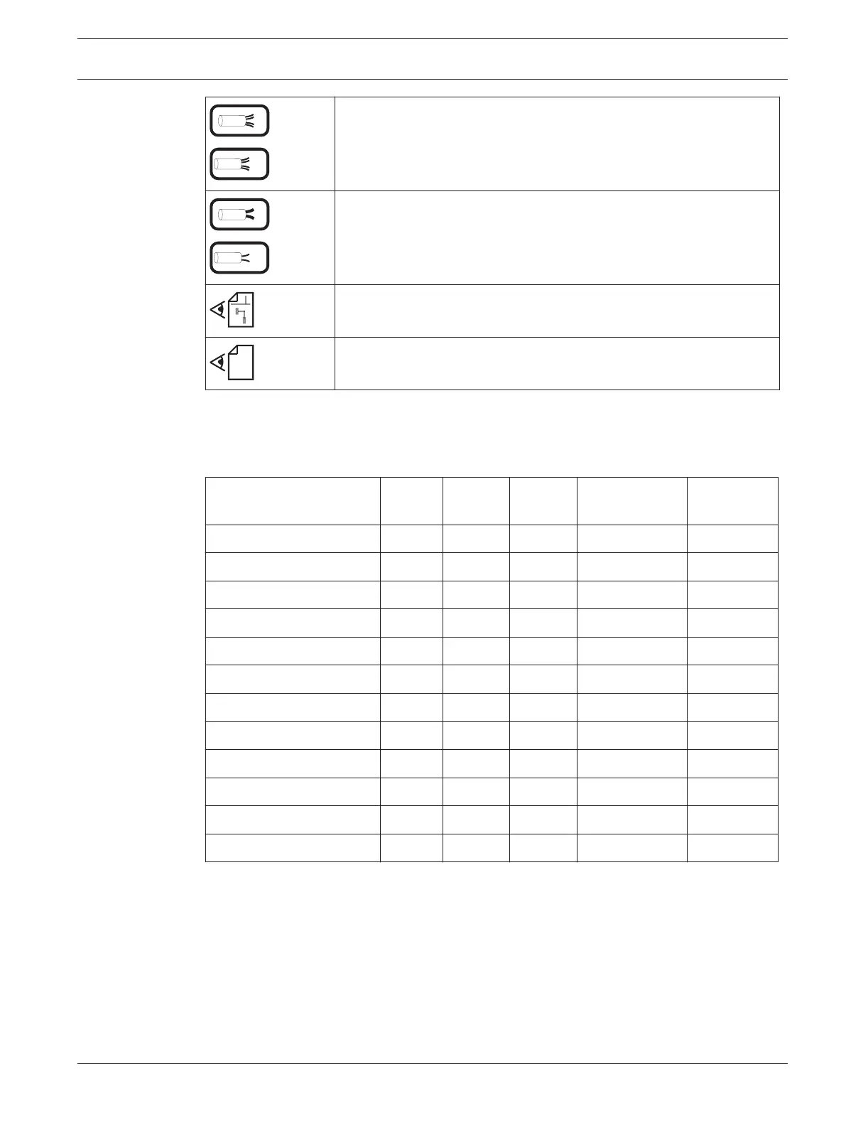
The wiring is a 4-wire connection.
Otherwise it is a 2-wire connection.
The wiring is a 2-wire connection.
See the wiring in this manual.
See the technical documentation of the connected peripheral device.
Resistance Values
The following table provides an overview of resistor color coding. The metal film resistors
delivered with the product have 5 color loops, which indicate the resistance value.
Color 1. Loop 2. Loop 3. Loop 4. Loop
(multiplicator)
5. Loop
(tolerance)
Silver 10
-2
Gold 10
-1
Black 0 0 10
0
Brown 1 1 1 10
1
±1%
Red 2 2 2 10
2
±2%
Orange 3 3 3 10
3
Yellow 4 4 4 10
4
Green 5 5 5 10
5
±0.5%
Blue 6 6 6 10
6
±0.25%
Purple 7 7 7 10
7
±0.1%
Gray 8 8 8 10
8
±0.05%
White 9 9 9 10
9
In accordance with IEC Publ. 62/DIN 41429
Orange — white — black — brown — brown: 3.9 k Ohm resistor with 1% tolerance,
Red — red — black — brown — brown: 2.2 k Ohm resistor with 1% tolerance.
2.5
Modular Fire Panel Notes | en 17
Bosch Sicherheitssysteme GmbH Wiring Guide 2016.07 | 12.6 | F.01U.009.201

 Loading...


