Do you have a question about the Bosch CC488 and is the answer not in the manual?
Details how system programming options are stored in non-volatile EPROM and can be changed.
Explains the procedure to enter and navigate Installer's Programming Mode using a codepad.
Provides instructions for arming and disarming the system in AWAY and STAY modes.
Guides users on entering and using Walk Test Mode to test zones.
Covers programming phone numbers, handshake tones, and transmission formats for receivers.
Details programming user codes and their associated authority levels for system access.
Explains how to configure zones, including zone types, pulse counts, and options.
Configures various reporting options for system events, including open/close and status reports.
Illustrates the wiring diagram for connecting the RF Receiver to the control panel.
Describes the module's operational status based on LED conditions.
Shows the layout and button functions of the 2-button RF keyfob.
Shows the layout and button functions of the 4-button RF keyfob.
Details wiring diagrams for 8 burglary zones using split EOL resistors.
Illustrates a split EOL wiring diagram for zone configuration.
Shows wiring diagrams for 8 zones using Normally Open (N/O) contacts.
Provides the wiring diagram for a keyswitch zone configuration.
Illustrates the overall wiring diagram for the Solution Ultima Series system.
Provides an overlay diagram showing the location and function of system components.
Shows connection diagrams for Master and Addressable CP-5 codepads.
Illustrates connection diagrams for two CP-5 Area Addressable codepads.
| Type | Control Panel |
|---|---|
| Model | CC488 |
| Manufacturer | Bosch |
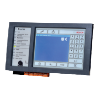
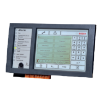
| Display | LCD |
| Compatibility | Bosch security systems |
| Power Supply | 16.5V AC/DC |
| Backup Battery | 12V 7Ah |
| Partitioning | Yes |