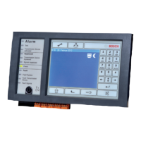
CC488 | Quick Reference Guide | 2.0 Programming Parameters EN | 19
Bosch Security Systems | 6/04 | 4998152446B
2.14.14 Speaker Beep Volume
Location
435
Default
13
0
15
No Beeps
Loudest Beeps
2.15 Options Programming
2.15.1 System Options 1
Location
436
1 Bosch Security Systems smart lockout allowed
2 Horn speaker monitor
4 Strobe indication for radio arm/disarm
8 Assign button 4 on transmitter to operate STAY Mode 1
2.15.2 System Options 2
Location
437
Default
0
1 Codepad panic to be silent
2 Codepad fire to be silent
4 Codepad medical to be silent
8 Access denied (code retries) to be silent
2.15.3 System Options 3
Location
438
1 AC fail after 1 hr. (Disabled = after 2 min.)
2 Ignore AC fail
4 Pulse count handover allowed
8 Handover delay to be sequential
2.15.4 System Options 4
Location
439
Default
0
1 Panel to power up disarmed (if power reset)
2 Arm/disarm tracking on power up
4 Internal crystal to keep time
8 Radio keyswitch interface, night arm station, or RE005
installed
2.15.5 Consumer Options 1
Location
440
Default
0
1 Test reports only when armed
2 Test report after siren reset
4 Auto arm in STAY Mode 1
8 STAY indicator to display day alarm status
2.15.6 Consumer Options 2
Location
441
1 Codepad displays extinguish after 60 sec.
2 Single button arming allowed (AWAY/STAY Modes 1 and
2)
4 Single button disarming allowed (STAY Modes 1 and 2)
8 Alarm memory reset on disarm
2.15.7 Consumer Options 3
Location
442
1 Codepad fault beeps allowed
2 Use digit 3 for codepad duress alarm (instead of digit 9)
4 Alarms activate sirens and strobe outputs in STAY
Modes 1 and 2
8 Zone tamper alarms to be silent
2.15.8 Radio Input Options
Location
443
Default
0
1 RF Receiver (RF-3212/E) connected
2 Latching keyswitch input
3 Momentary keyswitch input
4 Reserved
2.15.9 Partitioning Options 1
Location
444
Default
0
1 First to Open/Last to Close reporting armed
2 Area 1 codepad connected to data terminal
4 Reset sirens from any area allowed
8 Master codepad to display AUX indicator when online
2.15.10 Partitioning Options 2
Location
445
Default
0
1 Lock area 1 to Receiver 1 and lock area 2 to Receiver 2
2 User codes allowed to arm/disarm both areas at same time
(Code [0][#])
4 Reserved
8 Reserved
2.16 Zone Allocations Programming
2.16.1 Zone Allocations for Area 1
Location
446 to 453
Location Default
Zone 1 LED – Area 1 Codepad 446 0
Zone 2 LED – Area 1 Codepad 447 0
Zone 3 LED – Area 1 Codepad 448 0
Zone 4 LED – Area 1 Codepad 449 0
Zone 5 LED – Area 1 Codepad 450 0
Zone 6 LED – Area 1 Codepad 451 0
Zone 7 LED – Area 1 Codepad 452 0
Zone 8 LED – Area 1 Codepad 453 0
2.16.2 Zone Allocations for Area 2
Location
454 to 461
Location Default
Zone 1 LED – Area 2 Codepad 454 0
Zone 2 LED – Area 2 Codepad 455 0
Zone 3 LED – Area 2 Codepad 456 0
Zone 4 LED – Area 2 Codepad 457 0
Zone 5 LED – Area 2 Codepad 458 0
Zone 6 LED – Area 2 Codepad 459 0
Zone 7 LED – Area 2 Codepad 460 0
Zone 8 LED – Area 2 Codepad 461 0