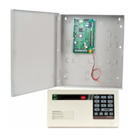
Do you have a question about the Bosch ICP-CC408 and is the answer not in the manual?
Lists the key features and capabilities of the ICP-CC408 security system.
Provides initial setup steps for the control panel using factory default settings.
Detailed instructions for programming the system using a remote codepad interface.
Explains how to use the CC891 programming key for data transfer and backup.
Method for selecting and combining programming options by summing bit numbers.
Lists and describes commands for installer-level programming and system testing.
Procedure to prevent unauthorized factory default resets, enhancing system security.
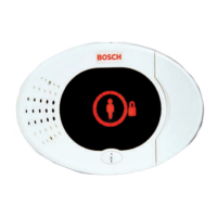
Details on the eight-zone LED codepad's indicators and interface for system status.
Explains the LCD codepad's display and indicators for system operation.
Information on the Master Partitioned LED codepad for managing partitioned systems.
Steps for arming the system in AWAY mode, essential for security when leaving premises.
Procedure to disarm the system from AWAY mode to disable detection devices.
How to arm the system in STAY Mode 1, securing the perimeter while allowing internal movement.
Instructions for arming the system in STAY Mode 2, enabling movement within isolated areas.
Method to manually disable zones before arming, preventing alarms from specific sensors.
Process for diagnosing system faults by interpreting codepad indicators and beeps.
Visual and audible feedback from the system during remote transmitter operations.
Assigning priority levels to remote radio transmitters to control system access.
Procedures for managing remote radio transmitter codes for system access.
Operations for the 2-channel transmitter, including arming, disarming, and panic alarms.
Operations for the 4-channel transmitter, including remote output control.
Accessing and using installer-specific functions for system tests and maintenance.
Configuring when the system sends its first test report for dialer verification.
How to view and program telephone numbers for domestic dialing and alarm reporting.
Selecting zones to be automatically isolated when the system is armed in STAY Mode 2.
Performing supervisory functions using the Master Code, such as managing user codes and system settings.
Activating specific operations by holding down codepad buttons for ease of use.
Instructions for remotely arming the system using a touch-tone telephone for enhanced security.
Establishing a remote connection to the control panel via telephone for programming and service.
Configuring settings for Alarm Link software, including upload/download and callback features.
Explains how the system dials telephone numbers for domestic reporting, including call sequences.
Simple process for configuring domestic reporting using Command 965.
Overview of available transmission formats for dialing and communication features.
Details of the Contact ID format, including event qualifiers and codes.
Explanation of the 4+2 reporting format, including Subscriber ID and Expansion Code.
Setting up basic pager reporting and interpreting displayed information.
Programming primary phone numbers for base station receiver communication, including retry logic.
Configuring secondary phone numbers for backup communication if primary numbers fail.
Selecting handshake tones required for data transmission to the monitoring station.
Choosing the data format for transmitting information to the base station receiver.
Entering the panel's unique identifier for the monitoring station.
Activating call diversion automatically when arming the system for call redirection.
Setting the number of rings before the panel answers calls, managing answering machines.
Configuring system indications and responses to a disconnected telephone line.
Settings for dialer reporting, remote arming, answering machine bypass, and FSK format.
Options for Open/Close reports, siren delay, and handshake time extension.
Configuring Alarm Link software settings for remote access and data transfer.
Details and usage of the Installer Code for accessing programming and maintenance functions.
Information on User Codes for system arming, disarming, and performing specific functions.
Assigning priority levels to User Codes to control access and permissions for system operations.
Configuring zones for monitoring while the system is disarmed, providing customer presence indications.
Setting the global End-of-Line resistor value for all zones, affecting detection and tamper resistance.
Detailed programming parameters for each zone, including type, pulse count, options, and reporting.
Setting the number of siren activations before lockout, preventing continuous alarm activation.
Configuring dialer activations before lockout, managing repeated failed communication attempts.
Configuring reports for zone bypass and restore events, indicating manual zone isolation.
Settings for zone trouble reports, indicating issues like unsealed zones or sensor faults.
Configuring sensor watch reports for detecting potential device failures.
Enabling and configuring reports for system arming (Closing) and disarming (Opening) events.
Enabling reports for duress alarms activated via codepad, serving as a silent holdup signal.
Configuring panic alarm reports sent to the base station upon codepad activation.
Setting up fire alarm reports sent to the base station upon codepad fire alarm activation.
Configuring medical alarm reports sent to the base station upon codepad medical alarm activation.
Configuring reports for main power (AC MAINS) failures, indicating power outages.
Configuring reports for low backup battery conditions, indicating a potential power failure.
Enabling reports for access denied events triggered by multiple incorrect code entries.
Programming the time and frequency for sending test reports to verify dialer functionality.
How to direct output event types to the codepad buzzer for additional event notifications.
Listing and explaining the various output event types for configuring system behavior.
Understanding output polarities to determine how outputs operate based on event occurrences.
Calculating output timing using time base and multiplier parameters for precise operation.
Setting entry and exit timers for arming/disarming delays, crucial for system usability.
Delay time for zones in STAY Mode, overriding programmed zone delay times.
Configuring the period zones remain sealed before triggering a sensor watch fault.
Setting the duration for codepad lockout after invalid code entries, enhancing security.
Programming the time of day for automatic system arming in AWAY Mode.
Setting the time of day for the system to automatically disarm.
Configuring smart lockout, horn speaker monitoring, and radio arm/disarm indications.
Settings to make codepad alarms (panic, fire, medical, access denied) silent.
Options for AC fail reporting delays, ignoring AC fail, and handover sequences.
Options related to panel power-up, arm/disarm tracking, and accessory compatibility.
Settings for test reports, auto-arming in STAY Mode 1, and STAY indicator for Day Alarm.
Options for codepad display timeout, single-button arming/disarming, and alarm memory reset.
Selecting options for radio receivers and keyswitch inputs for remote control.
Details on the Master Partitioned LED Codepad for operating partitioned systems.
Guidance on using Area Addressable and Master Partitioned codepads in partitioned systems.
Programming locations 432 and 433 for partitioned system options.
Allocating zones to specific areas for display and operation in partitioned systems.
Assigning User Codes to specific areas for operation within partitioned systems.
Step-by-step guide for setting up codepads in partitioned system configurations.
Using hand-held transmitters with an RF receiver for remote system operation.
Interface allowing radio control and use of multiple radio user codes.
Key for copying and storing control panel programming data for easy transfer.
Software for remote programming and control of the ICP-CC408 Control Panel.
Codepad for partitioned systems, selectable for Area 1 or Area 2.
Codepad for partitioned systems, allowing operation of both areas by toggling.
Station for arming/disarming in STAY Mode 1 from a remote location.
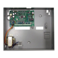
Power supply unit for the control panel, featuring overload protection.
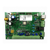
Detailed explanation of each terminal connection on the control panel for system components.
Definitions of key terms used in the manual for better understanding of system functions.
Visual wiring diagrams illustrating the connection of system components.
Explanation of the anti-jamming feature and its effectiveness in different telephone network environments.
Information on optimizing test report generation by sending them only when the system is armed.
Details regarding the product's warranty coverage, limitations, and manufacturer's responsibilities.
Procedure to display the control panel's software version number using specific commands.
Important user advice and conditions related to product usage and power supply.
Default values and location references for programming primary telephone numbers for Receiver 1.
Default values and location references for programming secondary telephone numbers for Receiver 1.
Default values and location references for selecting handshake tones for Receiver 1.
Default values and location references for selecting transmission formats for Receiver 1.
Default values and location references for programming the Subscriber ID Number for Receiver 1.
Table of country codes for PSTN line interface to meet international telephone line requirements.
| Part No | ICP-CC408 |
|---|---|
| No of Points | 8 |
| No of onboard zones | 8 |
| Partitions | 1 |
| Battery Backup | 12 VDC, 7 Ah |
| Communication | PSTN |
| Weight | 1.4 kg |
| Zones | 8 onboard, expandable to 16 |
| Outputs | 2 |
| Power Supply | 16.5 VAC, 40 VA |
