ICP-CC408 | Installation Guide | 19.0 Partitioning EN | 85
Bosch Security Systems, Inc. | 12/08 | F01U089463-02
19.6 Setting Up and Programming
Codepads for Partitioning
Only the CP5 Area Addressable (CP500AW) and
CP5 Master Partitioned (CP500PW) Codepads can
be used with a partitioned ICP-CC408 Control Panel.
19.6.1 Setting Up the Master Partitioned
Codepad as the Main Codepad
To use the CP5 Master Partitioned (CP500PW)
codepad as the main codepad in a partitioned
system, connect the codepad to the main codepad
terminals (CP-, CP+, CLK, and DATA). Set all DIP
switches on the back of the codepad to the ON
position.
19.6.2 Setting Up an Area 1 Codepad as the
Main Codepad
If you are not using the CP5 Master Partitioned
Codepad as the main codepad of the partitioned
system, connect the Area 1 codepad to the main
codepad terminals (CP-, CP+, CLK, and DATA). Set
DIP switch 1 on the back of the codepad into the ON
position and select Option 2 in Location 432 (refer to
Section 19.3.1 Partitioning Options 1 on page 82).
19.6.3 Setting Up an Area 1 Codepad
If you want a separate area codepad only for Area 1
when using the CP5 Master Partitioned Codepad as
the main codepad, connect the Area 1 codepad to
the main codepad terminals (CP-, CP+, and CLK)
and connect the DATA terminal to one of the
outputs programmed as 6,0 Area 1 Codepad Data
(refer to page 73). Set DIP Switch 1 on the back of the
Area 1 codepad to the ON position.
19.6.4 Setting Up an Area 2 Codepad
If you want a separate area codepad only for Area 2,
connect the Area 2 Codepad to the main codepad
terminals (CP-, CP+, and CLK) and connect the
DATA terminal to one of the outputs programmed as
6,1 Area 2 Codepad Data (refer to page 73). Set DIP
Switch 2 on the back of the Area 2 codepad to the
ON position.
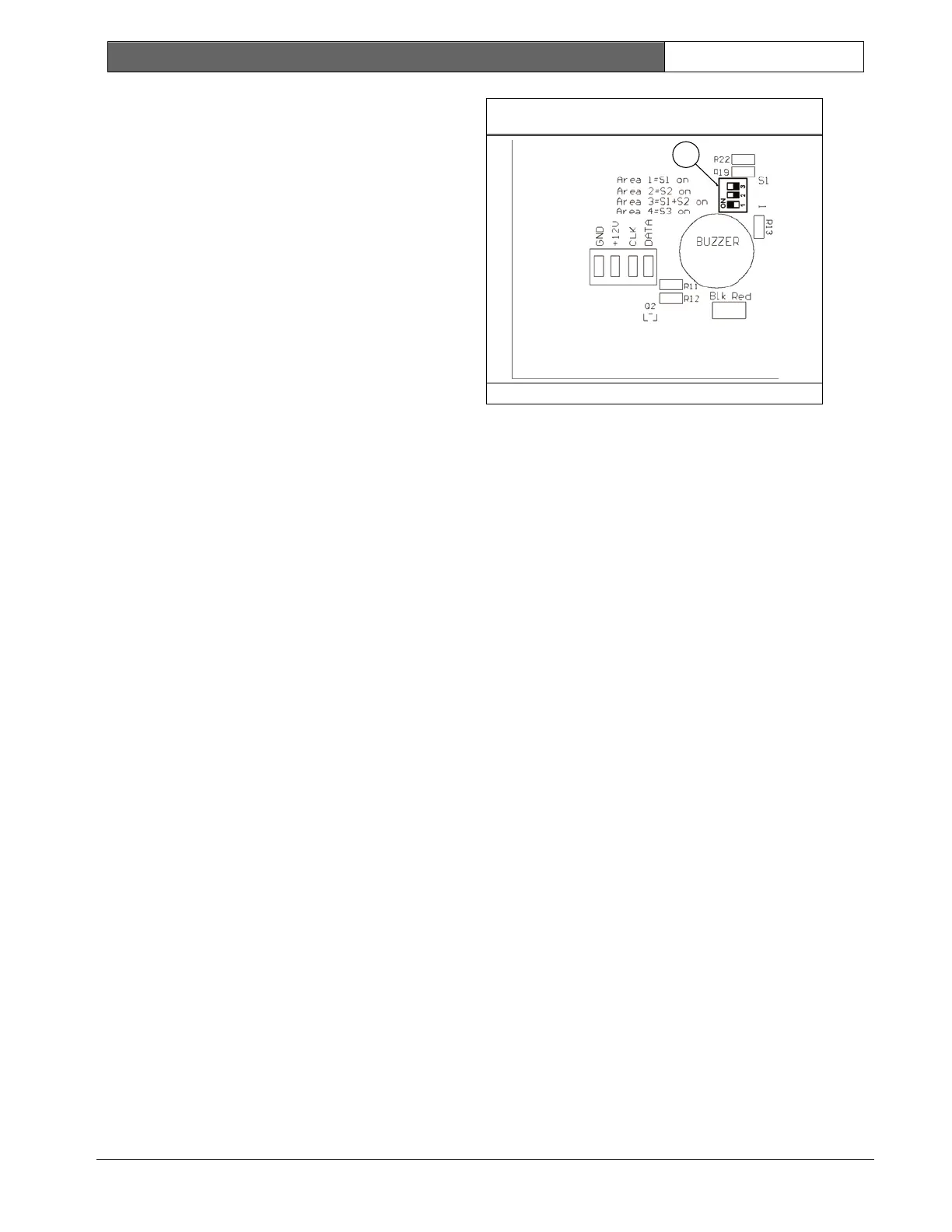
Figure 16: DIP Switch Location on Codepad
1
1 – DIP Switches
19.7 Codepad Connections For
Partitioning - Examples
If the CP-5 Area Addressable (CP500AW) Codepad
is assigned to Area 1:
1. Set DIP Switch 1 on the back of the remote
codepad to the ON position.
2. For Output 1, program Location 368 to 6 and
Location 369 to 0 (refer to page 73).
If the CP-5 Area Addressable (CP500AW) Codepad
is assigned to Area 2:
1. Set DIP Switch 2 on the back of the remote
codepad to the ON position.
2. For Output 1, program Location 368 to 6 and
Location 369 to 1 (refer to page 73).

 Loading...


