CC488 | Quick Reference Guide | 6.0 Wiring Diagrams EN | 24
Bosch Security Systems | 6/04 | 4998152446B
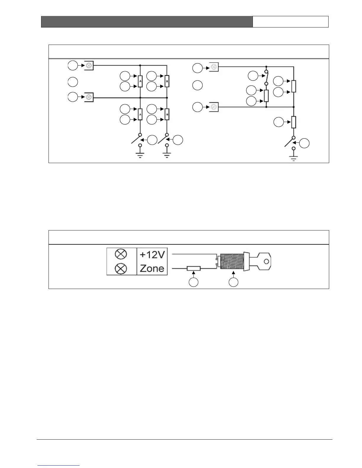
5.2 8 Zone Operation Using N/O Contacts
Figure 6: Split EOL Wiring Diagrams Using N/O Contacts
2
2
1
3
3
1
4
5
4
6
4
7
4
8
99
4
5
4
6
8
9
10
1 = +12 V
2 = Zone Input
3 = Zone
4 = EOL
5 = 3k3
6 = 6k8
7 = 1k5
8 = 4k7
9 = N/O
10 = N/C
6.0 Wiring Diagrams
6.1 Keyswitch Zone
Figure 7: Wiring Diagram for Keyswitch Zone
1 2
1 = EOL
2 = Keyswitch (Momentary/Toggle)