English–71 609 929 F69 • (04.10) PS
3 FUNCTION
While reading the operating instruc#
tions, refer to the corresponding illus#
trations of the electro#tool on the front
pages.
Intended Use
The electro#tool is intended as a stationary machine for
performing lengthways and crossways straight cuts in
wood or similar materials.
Also possible are horizontal mitre angles of 52° (left
side) to 60° (right side) as well as vertical bevel angles
of 47° (left side) to 46° (right side).
Noise/Vibration Information
Measured values are determined according to stand#
ard EN 61 029 procedures.
The A#weighted noise levels of the tool are typically:
Sound pressure level: 94.7 dB(A)
Sound power level: 107.7 dB(A)
Measurement uncertainty K = 3 dB
Wear ear protection!
The hand#arm vibration is typically below 2.5 m/s
2
.
Product Specifications
Switch#on actions cause brief drops in the mains volt#
age. For unfavourable mains conditions, interference
with other equipment can occur.
For mains impedance of less than 0.15 Ω, no interfer#
ence can be expected.
Product Elements
The numbering of the machine elements refers to the
illustrations of the electro#tool on the front pages of the
operating instructions.
1 Dust bag
2 Transport handle (front)
3 Clamp for the handle
4 Lever for adjusting the inclination of the handle
5 Handle
6 Button for unlocking the locking lever 41
*
7 Saw blade
8 Swinging guard
9 Roller
10 Table insert
11 Locking clamp
12 Locking knob for variable mitre angles (horizontal)
13 Lever for mitre angle adjustment (horizontal)
14 Clamping handle for variable bevel angle (vertical)
15 Detents for standard mitre angles
16 Saw table
17 Mounting holes
18 Fence
19 Fence extension
20 Locking knob for the fence extension
21 Quick action clamp
22 Angle indicator (vertical) for the right bevel angle
range
23 Slide rails
24 Cable holder
25 On/Off switch
26 Transport locking pin
27 Adjustment screw for the depth stop
28 Carrying handle (rear)
29 Locking screw for the slide rails
30 Scale for the bevel angle (vertical)
31 Angle indicator (vertical) for the left bevel angle
range
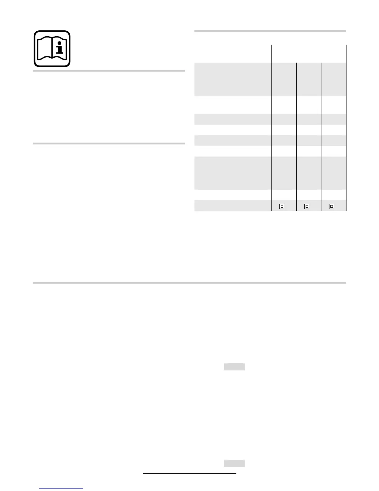
DualBevel
Slide Mitre Saw
GCM 10 SD
PROFESSIONAL
Order number
0 601 B22 …
… 503
… 508
… 532
… 542
… 537 … 541
Rated input
power
[W] 1 800 1 800 1 450
Voltage [V] 230 240 110
Frequency [Hz] 50 50 50
No load speed [min
#1
] 5 000 5 000 4 500
Tool spindle [mm] 30 25.4 30
Weight
(according to
EPTA Procedure
01/2003)
[kg] 27 27 27
Saw blade ∅ [mm] 254 254 254
Protection class / II / II / II
For maximum work piece dimensions,
see the "Working Instructions" Section
0-45°
45°-0