Troubleshooting | 33SM Series Heat Pump
8733942411 (2017/06)Revised 07-17
TROUBLESHOOTING
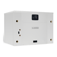
SM Series Water Source Heat Pump is equipped with a
externally mounted LCD screen that displays unit errors.
(Figure #64)
Figure # 64
Troubleshooting Information Solution column may
reflect a possible fault that may be one of, or a
combination of causes and solutions. Check each
cause and adopt “process of elimination” and or
verification of each before making any conclusion.
UPM Board LED Indications
Indication
Color
Blinks Description
GREEN Solid 18-30 VAC Power is present
RED 1 High pressure lockout
RED 2 Low pressure lockout
RED 3 Coax Freeze sensor lockout
RED 4 Condensate overflow
RED 5 Brownout
RED 6 Evaporator Freeze lockout
Compressor Ohms
Model Start Winding Run Winding
SM024 1.64 1.3
SM036 1.50 0.85
SM048 1.90 0.53
SM060 1.68 0.42
SM070 1.91 0.36
Tolerance +/- 7%. All resistance values must be
measured with compressor at room temperature.
 Loading...