-14-
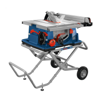
Getting to Know Your GTS18V-08 Table Saw
1 Power Switch is used to turn the tool on
and off. The Power Switch incorporates a
locking hasp for use with a padlock to pre-
vent accidental starting.
2 Elevation Wheel elevates or lowers the
blade. Use with Blade Bevel Lock Handle 3
to tilt the Blade 0° to 45°.
3 Blade Bevel Lock Handle locks the Blade to
de sired bevel angle.
4 Blade Bevel Scale shows the degree the
Blade is tilted.
5 Base supports the table saw. Holes in the
Base allow the saw to be bolted to a work-
bench or stand.
6 Rail Lock Lever allows you to lock the Rip
Fence 9 at the desired distance from the
Blade.
7 Rail Adjustment Knob is used to adjust the
position of the Rip Fence 9.
8 Push Stick is a device used to feed the
workpiece through the saw during narrow
ripping-type operation. It helps keep the
operator’s hands well away from the Blade.
9 Rip Fence attaches to the Rails 10 using the
locking latches and guides the workpiece
parallel to the blade.
10 Rails provide mounting points for the Rip
Fence 9 at the front and rear of the saw.
11 Smart Guard System consists of an adjust-
able three-position Riving Knife, an Anti-
Kickback Device, and a Barrier Guard As-
sembly. These are part of a modular system
that requires no tools to assemble or dis-
assemble. The Smart Guard System must
always be in place and working properly for
all through-sawing cuts.
12 Table Insert provides workpiece support
near the Blade. It can be removed to re-
move or install the Blade or other cutting
tools and to adjust or store the Riving Knife.
13 Table provides a large working surface to
support workpiece.
14 Miter Gauge head can be locked at the de-
sired angle for crosscutting or mitering by
tightening the Miter Gauge Lock Knob. AL-
WAYS SECURELY LOCK THE MITER GAUGE
WHEN IN USE.
15 Adjustment Handles may be used to help
in positioning the saw. They are not intend-
ed to be used as carry handles.
16 One-Handed Carry Handle is used to carry
the saw.
17 Fuel Gauge indicates the approximate level
of charge remaining in the Battery Pack.
18 Flip-Over Fence is attached to the Rip
Fence 9. The Flip-Over Fence, in the lower
position, provides material support and, in
the upper position, provides support for
workpieces 1/8 to 3/4 of an inch (3.2 to
20 mm) thick.
19 Dust Port/Vacuum Hook-Up allows you to
attach any 2-1/4” vacuum hose to the dust
port for convenient sawdust removal. An
adaptor is available for use with alternate
hose sizes.
1609B07947GTS18V-08 OSI 08-2022.indd 14 8/3/22 2:44 PM

 Loading...