-22-
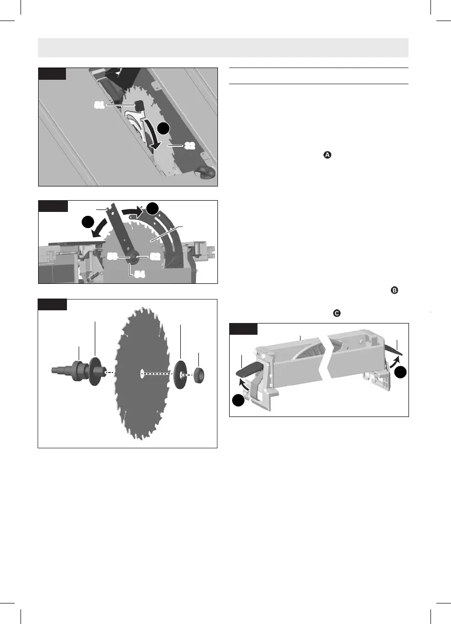
Attaching the Rip Fence
(Fig. 20, Fig. 21, Fig. 22, Fig. 23, Fig. 24, Fig.
25)
1. Make sure that the Rail Lock Lever 6 is in the
locked position.
2. Lift the Rip Fence Lock Levers 56 up on both
ends of the Rip Fence 9 so that they are in
the released position .
3. Orient the Rip Fence 9 over one of the three
Rip Fence Index Pin pairs, 57, 58, or 59, so
that the Flip-Over Fence 18, in its stored po-
sition, is facing away from the Blade 32 and
the Smart Guard System 11.
NOTE: For how to put the Flip-Over Fence 18
in its stored position, see “Rip Fence Stor-
age” on page 26.
4. Lower the Rip Fence 9 to the Rails 10 so
that the notches on the Rip Fence bracket 60
line up with the Rip Fence Index Pin pair that
you have selected, 57, 58, or 59, and lower
the Rip Fence 9 onto the Index Pin pair .
5. Latch the Rip Fence Lock Levers 56 on both
ends of the Rip Fence 9 .
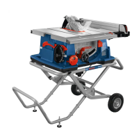
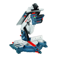
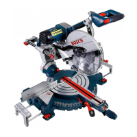
Assembly
27
53
52
32
54
B
C
Fig. 18
52
53
55
54
Fig. 19
56
56
A
A
9
Fig. 20
51
32
A
Fig. 17
1609B07947GTS18V-08 OSI 08-2022.indd 22 8/3/22 2:44 PM