Display Configuration | 10
Bosch Motorsport DDU 9 47/148
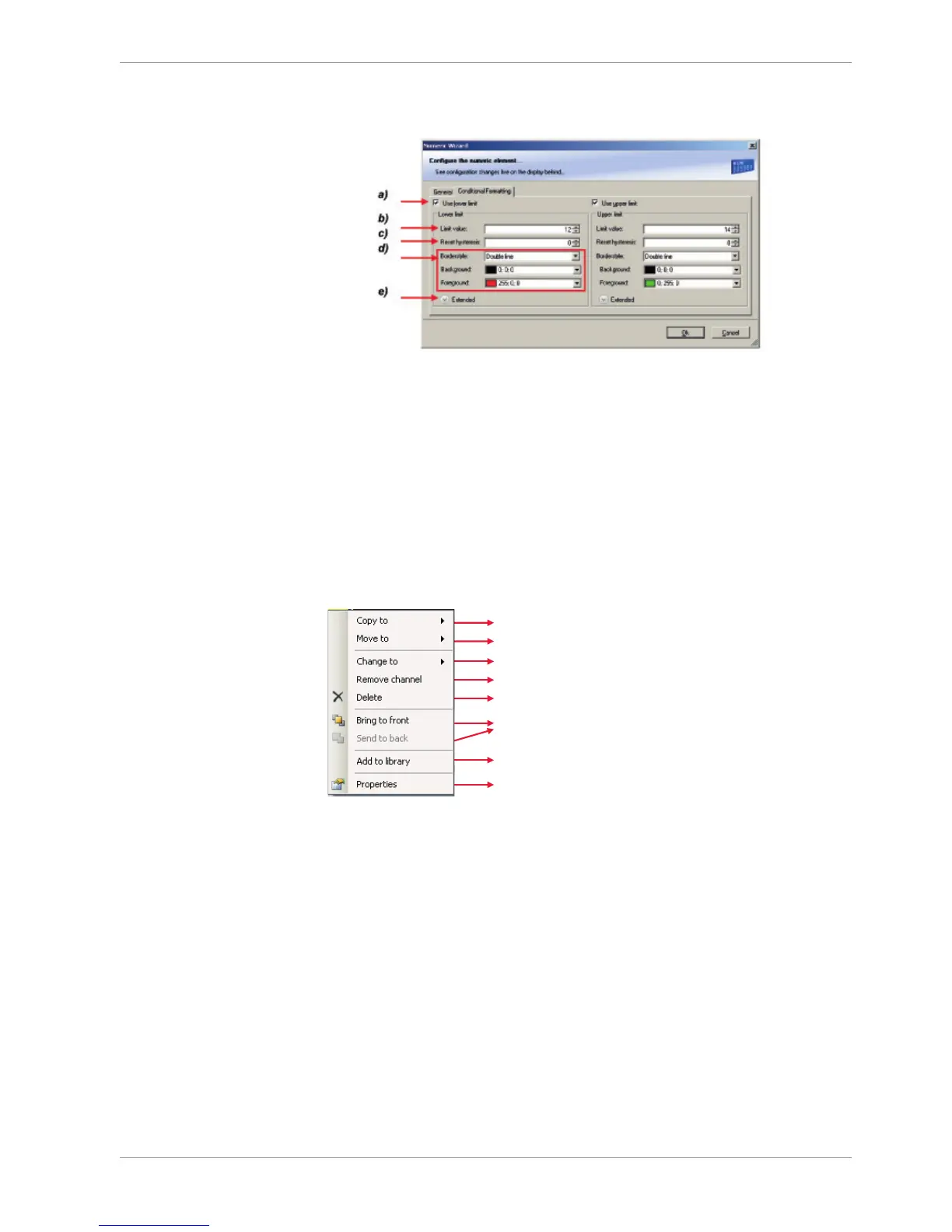
The lower and the upper limits are configured in the same way.
a) Check the box to activate the formatting at a lower limit.
b) Enter the limit value when the formatting is active.
c) Enter the limit value when the reset hysteresis function is active. The reset hysteresis function avoids the
high-frequent switchover of the measurement channel value.
d) Choose the borderstyle, background and foreground color of the numeric display element.
e) Click the Extended button to show further options to change the color of the title, border and text
individually. If a ‘Bargraph’ display element is used, its colors can also be changed.
3. Click ‘OK’ when done.
10.2.6 Context menu
The context menu appears by right-clicking on a display element.
Change type of display element
Move element to different page
Remove assigned measurement channel
Manage overlapping elements
Insert element into library in toolbox
Copy element to different page or all pages
10.3 LEDs
The LEDs are fully configurable to show the optimal shifting point. They can also be con-
figured to flash in case of a customized condition becoming ‘true’.
10.3.1 Configuring shift LEDs
To use shift LEDs, RPM and gear measurement channels an ECU has to be loaded in Race-
Con.
1. Click on the tab ‘LEDs’ in the display view.
2. Click on the button ‘Add shift lights’.
 Loading...