32/120 Bosch Rexroth AG KE350/KE350G IL | 3 609 929 B62/2009-02
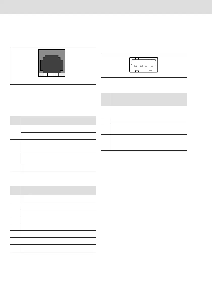
X7E1 Ethernet interface
The interface has an 8-pin RJ45 socket (10/
100 Base T) design.
Fig. 5: RJ45 socket, 8-pin
1 Yellow LED
2 Green LED
The MAC address can be found on the name
plate.
USB host interfaces (X3U1, X3U2)
These interfaces are designed as type A
sockets. They fulfill the requirements in USB
specification 2.0.
Fig. 6: USB socket, type
Tab. 5: LED states
LED State Display/description
1 Yellow Transfer speed 100 Mbit/s
Off Transfer speed 10 Mbit/s
2 Green Connection to network is
active
Green,
flashing
Data transfer running
Off No connection to network
Tab. 6: X7E1 assignment
Pin Signal Description/function
1 Transmit + Ethernet transmission cable
2 Transmit – Ethernet transmission cable
3 Receive + Ethernet reception cable
4 n.c.
5 n.c.
6 Receive – Ethernet reception cable
7 n.c.
8 n.c.
1
2
Tab. 7: X3U1, X3U2 assignment
Pin Signal Description/
function
Voltage/
current
1 VCC 5 V supply 5 V= /
0.5 A
2
USB_Data–
Send USB data
3
USB_Data+
Receive USB
data
4 GND Reference
potential for all
voltages
PE poten-
tial
1234
KE350.book Page 32 Friday, February 6, 2009 1:27 PM
 Loading...