36/120 Bosch Rexroth AG KE350/KE350G IL | 3 609 929 B62/2009-02
Control signals
The tightening cell communicates with the
superior controller via control signals. A PLC
assignment table determines which control
signals are assigned to the inputs/outputs.
The inputs/outputs are assigned in the
BS350 operating program.
Further information can be found in:
– the online guide in the operating program
(programming the assignment table),
– the system documentation, chapter 5
“Control signals” (3 609 929 918) (signal
description, sequence examples, and
chronological sequences).
8 Operation
Operation is not necessary while the system is
running.
9 Maintenance and
repair
Cleaning and care
Maintenance
The KE350/KE350G IL communication unit
is maintenance-free if used as intended.
Repair
Reset function
A software reset is generated if the reset
button is briefly pressed, i.e. for < 1 second.
The controller is reset once the button is
released.
A hardware reset is generated if the reset
button is pressed for a long period, i.e. for
> 3 seconds. The controller and servo
amplifier are reset once the button is
released.
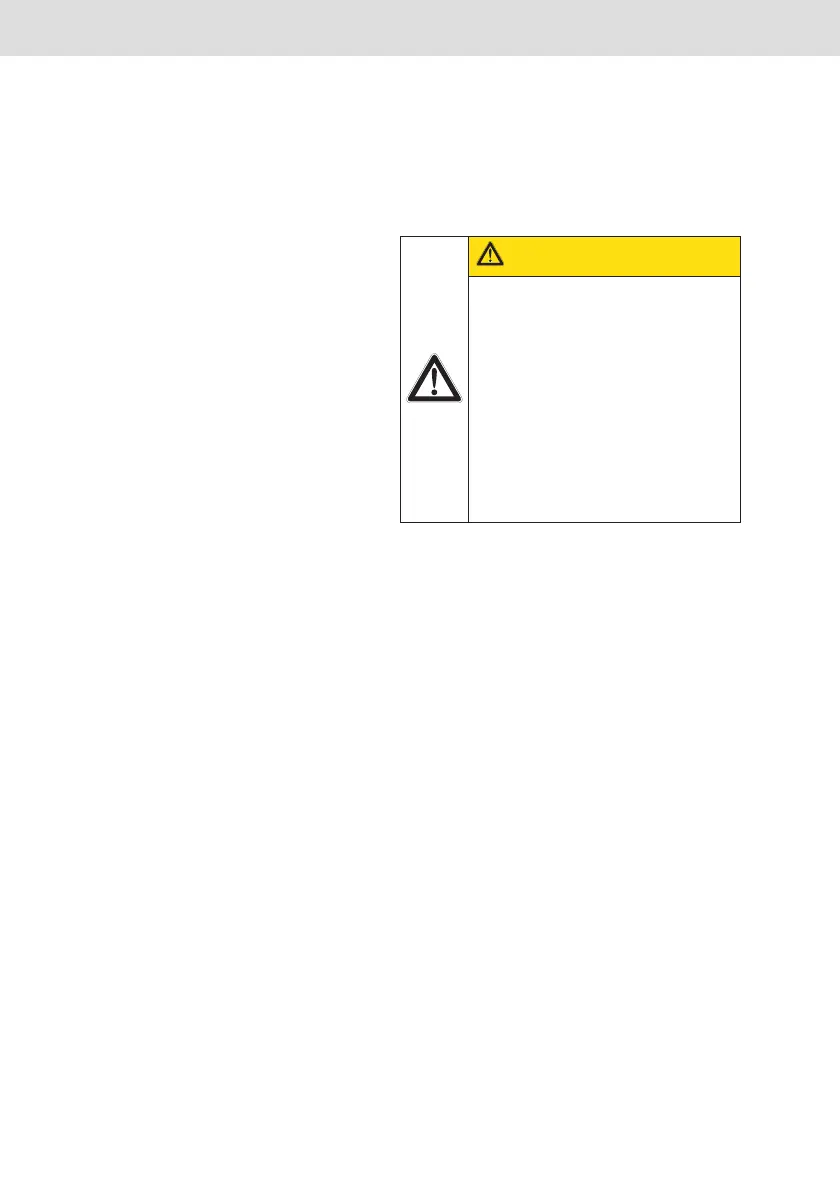
CAUTION
Any dirt or liquids penetrating
the device lead to
malfunctions!
The safe function of the KE350/
KE350G IL communication unit is
then no longer ensured.
y Always provide for absolute
cleanness when working on
the KE350/KE350G IL com-
munication unit.
KE350.book Page 36 Friday, February 6, 2009 1:27 PM




 To Next Page