PI - 32.15aProduct Documentation of the LSN Radio Fire Detection System
Seite 10 von 32
601-F.01U.002.708
A3.en / 28.12.2004
ST-FIR/ PRM1 / deh
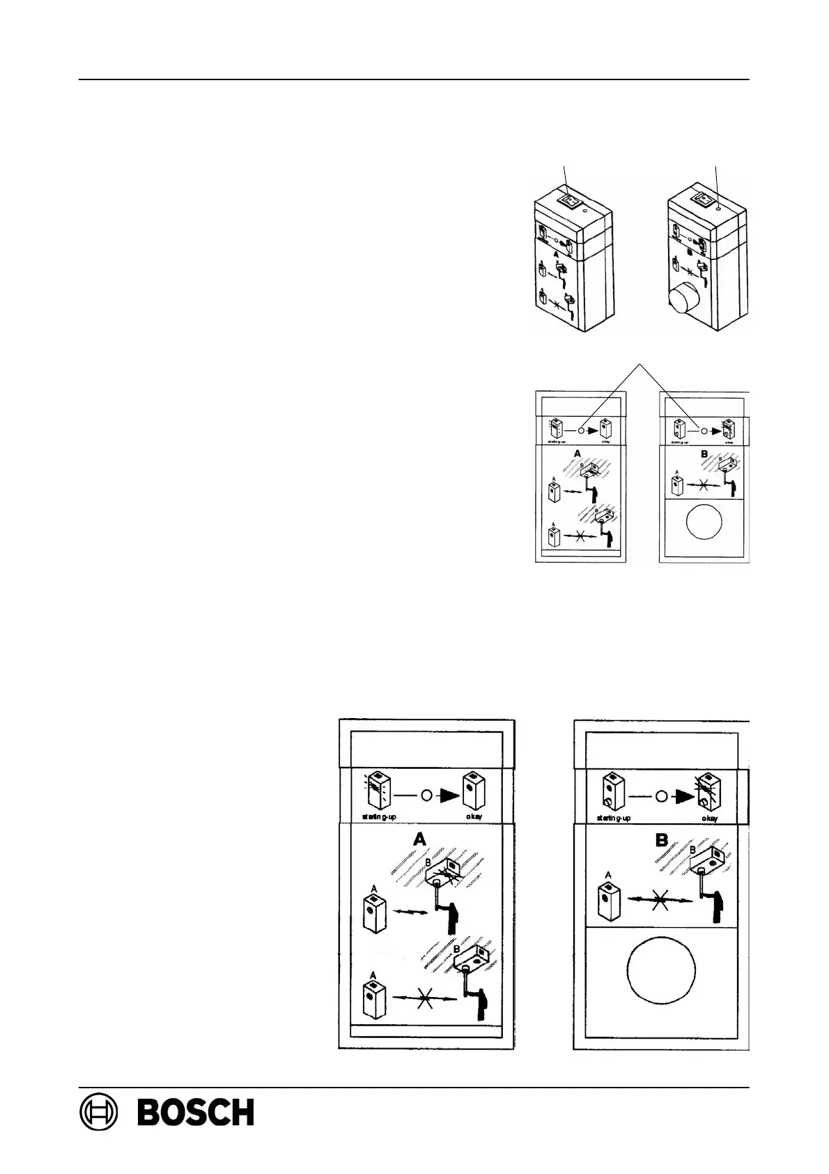
3.3. Field strength measurement with radio test device DZW 1171
D Switch on modules A and B.
⇒ The LEDs next to the switches light up if there is
sufficient battery voltage.
⇒ The specified radio connection between the
modules is initiated automatically and the LED on
module A flashes while the radio connection is
being established.
⇒ Once the radio connection has been successfully
established, the LED on module A and the LED on
module B light up permanently.
D Position module A as close as possible to the
RF expansion module.
D Connect module B to the service rod and move to
the required RF detector mounting location.
. The radio signal can be transferred all the while the
LED on module B is illuminated
(attenuation t 89dB).
. If the LED on module B starts to flash, the radio range limit has been reached
(attenuation 85dB). If the LED continues to flash, the radio signal is still strong
enough for trouble-free operation.
. If the LED on module B goes out, the mounting location of the RF expansion module
or the RF detector is outside the radio range.
Batt. LEDSwitch
LED
Module A Module B
Basic graphical
instructions (imprinted
on the modules)