PI - 32.15aProduct Documentation of the LSN Radio Fire Detection System
Seite 12 von 32
601-F.01U.002.708
A3.en / 28.12.2004
ST-FIR/ PRM1 / deh
5. Installation
5.1. Mounting Tips for RF expansion module FK 100 LSN
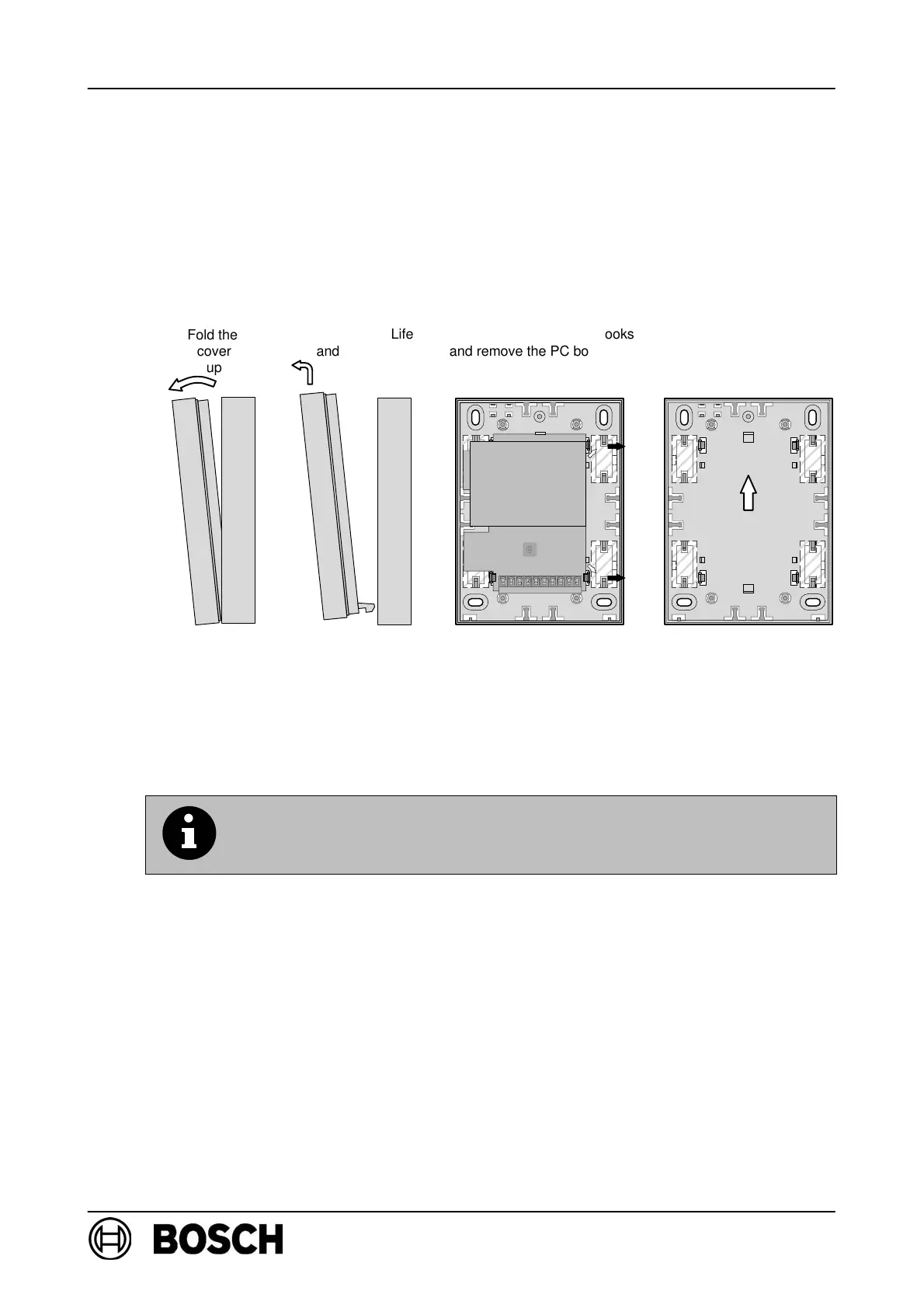
D The RF expansion module must only be installed in dry areas. The maximum per-
missible ambient temperature must also be observed (see ”Technical Data”). The
PC board, including the radio module, must removed before mounting. Carefully
bend back the snap-fit hooks to remove the PC board.
D With recessed cable feed, pre-punched openings are punched through on the base
of the lower part of the housing.
D With surface cable feed, pre-punched openings are punched through on the side
of the lower part of the housing.
D Mount the lower part of the housing on a dry surface using at least two screws.
If several FK 100 LSN RF expansion modules are mounted in the
same area, a minimum distance of 2m must be retained between
the individual RF expansion modules!
D Use cable ties to relieve the strain on the cable at the bars
(see assembly drawing on p.2) .
D After installation, replace the cover and secure it using the screw provided.
D Only use mounting materials specified by Bosch-ST; interference resistance can-
not otherwise be guaranteed.
D Caution! ESD (electrostatic discharge). The standard precautions for C-MOS
technology must be taken when handling PC boards.
D The connection criteria of the regional authorities /institutions (police, fire service)
must be observed.
Fold the
cover
up
Life
and remove the
cover
Bend back the snap-fit hooks
and remove the PC board and
radio module.
Up
Snap-fit hooks
en
moun
ng
on
a
wa
,
e
RF expansion module must be
mounted vertically as shown
by the markings on the cover.
Radio module
Snap-fit hooks
PC board