PI - 32.15aProduct Documentation of the LSN Radio Fire Detection System
Seite 21 von 32
601-F.01U.002.708
A3.en / 28.12.2004
ST-FIR/ PRM1 / deh
7. Initial Set-Up without Fire Panel and WinPara
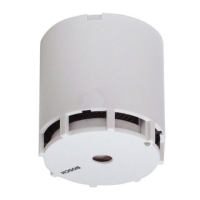
A permanent power supply to FK 100 LSN must be ensured when
performing initial set-up of a radio cell without fire panel.
. The LSN terminal block must not be connected to FK 100 LSN.
D Connect the expander power supply, e.g. by
connecting the terminal block.
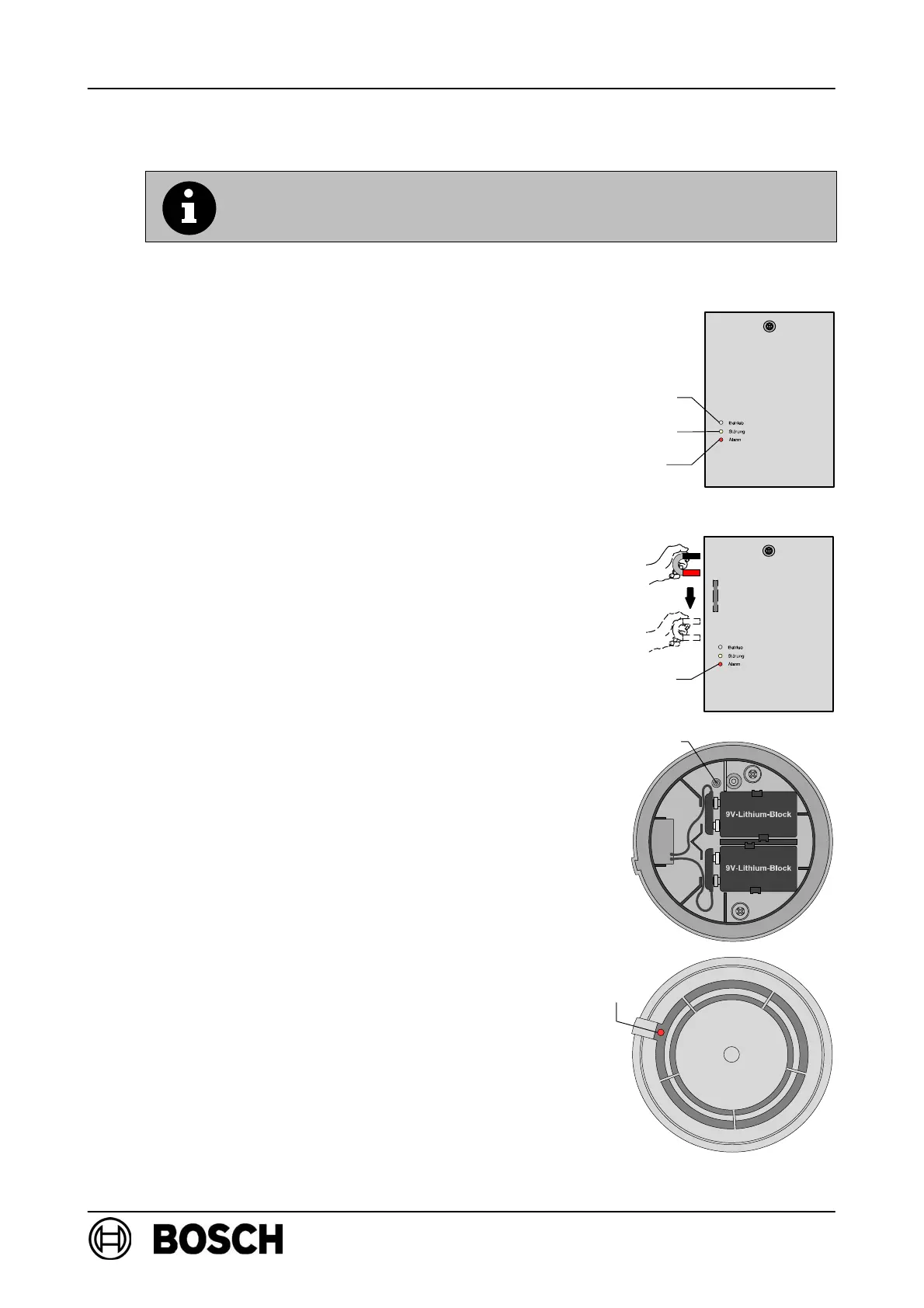
⇒ The red LED on FK 100 LSN lights up for a few
seconds.
⇒ The yellow LED flashes slowly, indicating that
FK 100 LSN is in standby mode.
D The reed switch on FK 100 LSN is activated, by
the magnets moving along the left-hand side of
the housing, for manual initial set-up of the radio
cell.
⇒ The red LED on FK 100 LSN lights up briefly, then
the green and yellow LEDs start to flash rapidly to
indicate a frequency search (max. 10 min.).
⇒ Following a successful frequency search, the
yellow LED goes out to indicate that it is now
possible to log on to the RF detector.
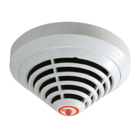
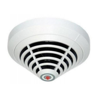
Log RF detector on to RF expansion module:
D Insert the batteries and secure the cables,
as shown in the diagram on the right.
⇒ The red LED must flash slowly.
D If the LED is flashing rapidly, press the new button
and hold it for at least 3 seconds.
⇒ The detector will be reset to its delivery status and
the LED will flash slowly.
D Insert the detector in the base within 10 minutes of
inserting the batteries!
LED green
LED yellow
LED red
red
Reed switch
LED
Button new
LED
red