PI - 32.15aProduct Documentation of the LSN Radio Fire Detection System
Seite 8 von 32
601-F.01U.002.708
A3.en / 28.12.2004
ST-FIR/ PRM1 / deh
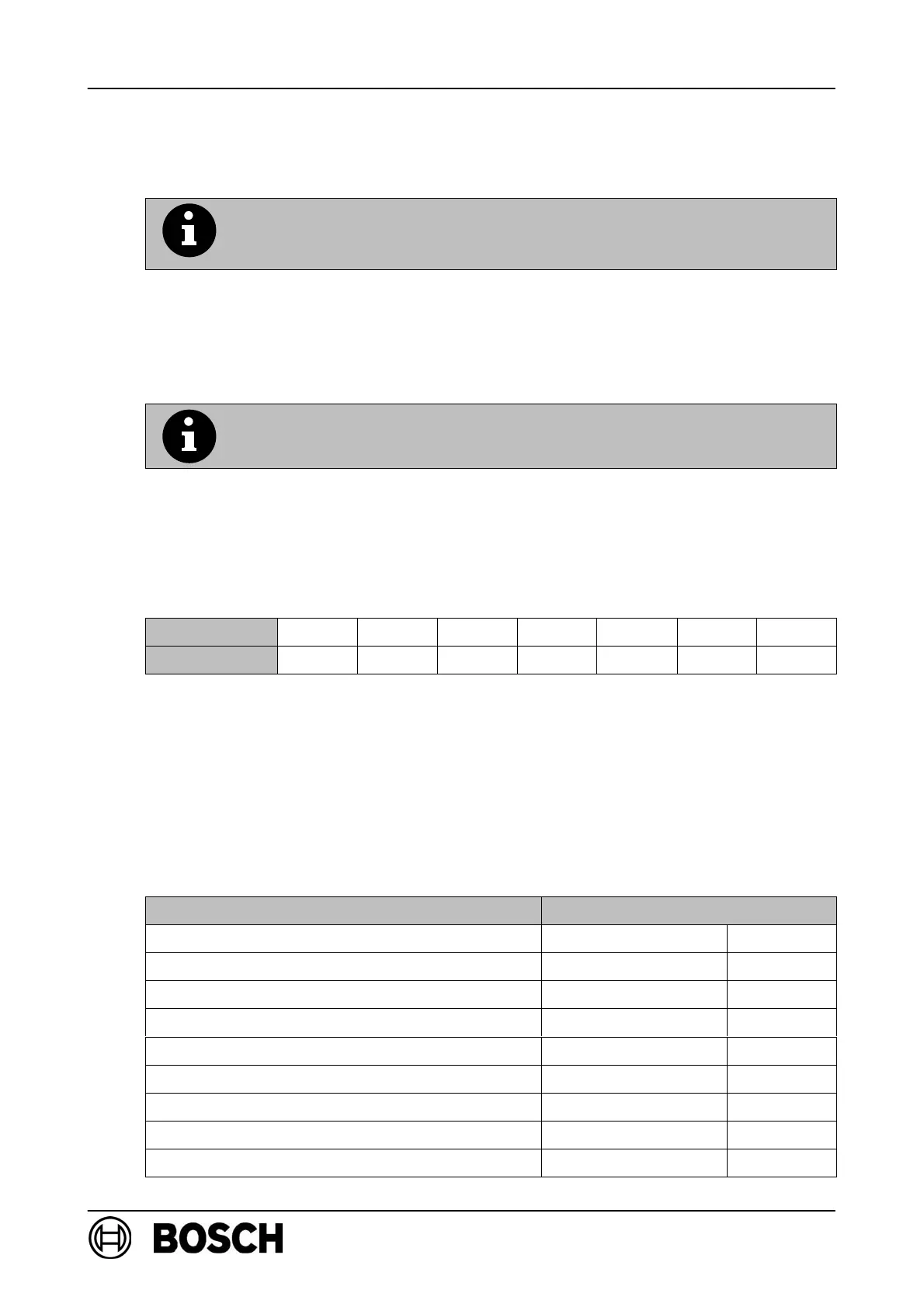
3.1. Planning a radio cell
The range that can be achieved by a radio system in a building is
generally dependent on the reflection and absorption responses of
the materials used and on the design of the ceilings and walls!
. There is no need for a visual line between the radio components!
Limiting value when planning a transmission path
Total attenuation of a transmission path < 90dB.
Relationship between distance and attenuation with a visual line
. In buildings, doubling the distance between the RF expansion module and the RF
detector results in an attenuation increase of 16 to 17dB.
Distance 40m 30m 25m 20m 15m 10m 5m
Attenuation 90dB 83dB 79dB 74dB 67dB 57dB 40dB
Walls and ceilings in buildings cause additional attenuation of the radio signal.
D The attenuation values of the construction elements in question (walls, ceilings)
must also be added to determine the actual attenuation at the mounting location in
the case of attenuation owing to the distance.
Attenuation values for constructions frequently used in buildings
Construction Additional attenuation
Partition Very low 1dB
Dry brick wall or concrete wall/ceiling Low 6dB
Lime sand brick Moderate 6dB
Sand lime brick planning elements Moderate 10dB
Wood skeleton wall/wood panel wall Moderate 10dB
Damp brick wall Moderate 10dB
Coated gypsum plasterboard (double wall) High 15dB
Reinforced concrete High 30dB
Thick, damp brick wall Very high 40dB