PI - 32.15aProduct Documentation of the LSN Radio Fire Detection System
Seite 5 von 32
601-F.01U.002.708
A3.en / 28.12.2004
ST-FIR/ PRM1 / deh
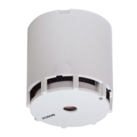
FK 100 LSN device description
Power is supplied to the LSN part in the RF expansion module via the LSN loop; the
attached radio module with radio license in line with ANNEX 4, Directive 99/5EC Radio
recognition requires a separate voltage supply.
The integrated microcontroller controls the interfaces and user elements and is responsi-
ble for data transmission between the wireless smoke detector and the fire panel.
FK 100 LSN has a tamper contact, a reed switch for manual activation of the configura-
tion mode and 3 LEDs for the operating status display.
The LSN - RF expansion module complies with the standard regulations and guide-
lines for security systems: EN 54; DIN - VDE 0833; VdS.
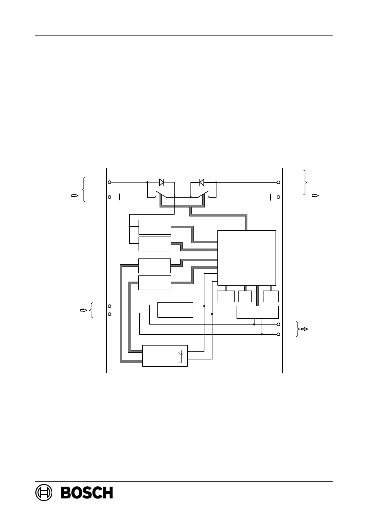
FK 100 LSN block diagram
Power
supply
Send
data
FET switch
Receive
data
b LSN2
b LSN2
LSN
LSN
a LSN1
a LSN2
+U
0V
Send
data
Receive
data
+U
0V
SPU6001
Radio
module
Reed-
switch
LEDs
Tamper
-
contact
Monitoring of ext.
power supply.
Microprocessor
for
-data transmission
-data processing
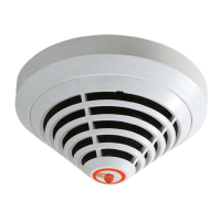
1.3. RF smoke detector DOW 1171 product description
The battery-operated programmable RF smoke detector works on the tried and tested
scattered light principle with lateral scattering and, in conjunction with a modern detec-
tion algorithm, achieves a homogeneous response behavior and outstanding interfer-
ence immunity. The same radio module as that used in the RF expansion module is
integrated in the detector for bi-directional information transfer.