PI - 32.15aProduct Documentation of the LSN Radio Fire Detection System
Seite 25 von 32
601-F.01U.002.708
A3.en / 28.12.2004
ST-FIR/ PRM1 / deh
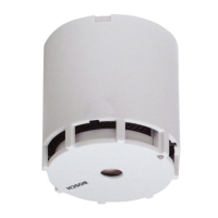
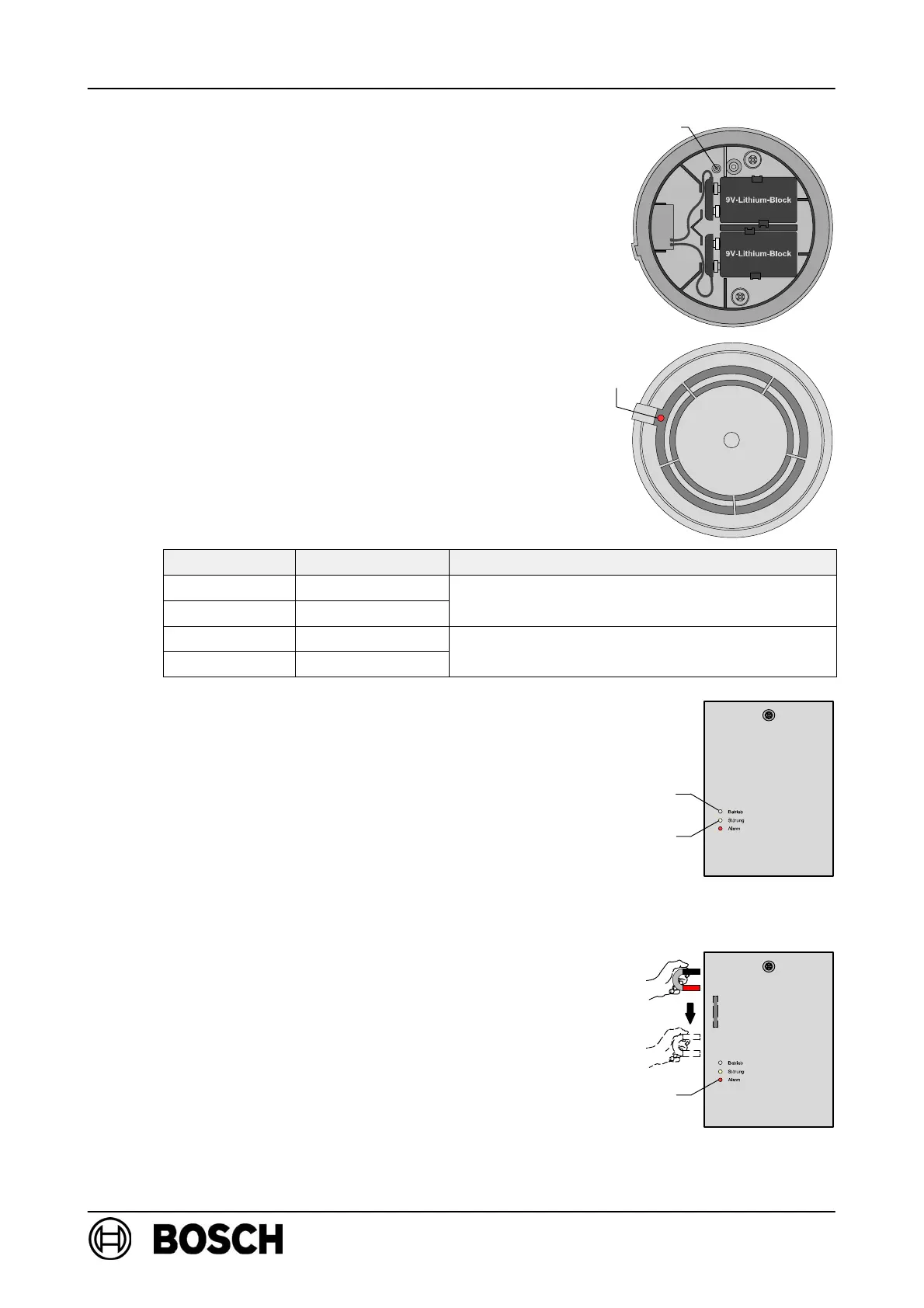
Log RF detector on to RF expansion module:
D Insert the batteries and secure the cables,
as shown in the diagram on the right.
⇒ The red LED must flash slowly.
D If the LED is flashing rapidly, press the new button
and hold it for at least 3 seconds.
⇒ The detector will be reset to its delivery status and
the red LED will flash slowly.
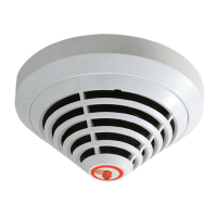
D Insert the detector in the base within 10 minutes
of inserting the batteries!
⇒ Following a successful system logon (duration:
15 sec. to a max. of 10 mins), the red LED will go
out and then flashes again for two minutes to
indicate the field strength.
Flashes/sec. Field strength Effect
4 High
Within field stren
th ran
e ade
uate for
3 Moderate
Within field strength range adequate for
detector use!
2 Low
Im
ermissible field stren
th ran
e!
1 Very low
Impermissible field strength range!
Improve detector positioning!
⇒ The yellow LED on the RF expansion module
lights up briefly to acknowledge successful logon
of the DOW 1171 to the RF expansion module.
D All additional RF detectors (up to a maximum of
30) are logged on to FK 100 LSN in this way one
after the other.
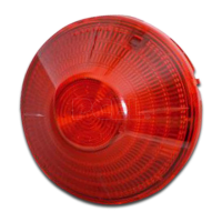
D Wait until the red LED (flashing to indicate field
strength) on the last detector goes out.
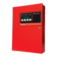
D Activate the reed contact on FK 100 LSN by mov-
ing the magnets along the left-hand side of the
housing.
⇒ The green LED flashes slowly, indicating that
FK 100 LSN has started system configuration.
⇒ Following successful system configuration, the
green LED lights up permanently, indicating that
the radio cell is in standard mode.
Button new
LED
red
yellowLED
greenLED
Reed switch
LED red