ENGLISH
R320103169/2020-08 | Linear modules MKK/MKR-xxx-NN-3 Bosch Rexroth AG 21/62
ca
caIMS
L
ms
(+) L
ms
(-)
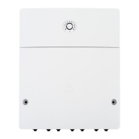
6.5.9 Solenoid switch position for magnetic sensor
Fig�22: Solenoid switch position for magnetic sensor
L
ca
/
L
caIMS
L
ms
(+)
Solenoid switch
position
MKK
Solenoid switch
position
f The switch activator (both sides) is amagnet that is built into the carriage (no switching cam necessary).
At versions with two carriages, the solenoid switch is always in carriage TT1.
The switch activation points can be positioned anywhere along the stroke.
The solenoid of linear modules MKR is integrated in + or - direction or centrally in the carriage
(depending on size, see table 6 and
fig. 22).
Table 6: Solenoid switch position in carriage
MKR/MLR
TT2TT1
W
W
TT2
TT1
L
ca
/
L
caIMS
(mm) L
ms
(mm) Solenoid switch
(Øxlength) (mm)
MKK
-040-NN-3 135 57.5
4 x 20
-065-NN-3 190 85
-080-NN-3
260 102.5
6 x 15
360 152.5
-110-NN-3
305 125
430 187.5
-140-NN-3
370 176
500 241
MKR
-040-NN-3 135 -60 4 x 12
-065-NN-3 190 -85
4 x 20
-080-NN-3
190 -65
260 0
360 50
-110-NN-3
210 -53
305 0
430 62.5
-140-NN-3
370 0
500 65
-145-NN-3 400 0
MLR
-080-NN-3 190 0 4 x 20
-110-NN-3 305 2.5 6 x 15