Configuration
All-in-One Unit configuration
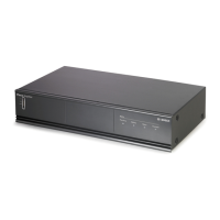
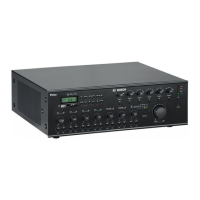
The following figure lists all items on the rear panel of the All‑in‑One Unit. This section only
describes the items used for configuring the All‑in‑One Unit. For information on connecting the
unit, refer to All‑in‑One Unit connections, page 14.
17 20
52
53
54
55
56
50 49
48 46
47
59
51
57
45
44
43
424138373534322221
16
18
19
30
40
3936333123 25
24
28
58
29
27
26
Figure 7.1: Rear panel
Number
Item Description
17 Mains line voltage selector A slider switch to select the AC line voltage (115 Vac/230 Vac) to the
mains voltage of the country where the unit is being used.
24 Mode selection – Single channel (Mode 1) - the internal power amplifier serves as
the power amplifier for both music and calls. An optional external
power amplifier, connected between terminals (51) and (57), will
act as a spare amplifier in case amplifier supervision is enabled
with switch (25). In single channel mode, music will be interrupted
when a call is made.
– Dual channel (Mode 2) - the internal power amplifier serves as the
power amplifier for the music channel, while the external power
amplifier, connected between terminals (51) and (57), serves as
the amplifier for the call channel. In case supervision is enabled
with switch (25), the internal power amplifier will also serve as a
spare amplifier for the call channel. In dual channel mode, zones
with music will not be interrupted by calls to another zone.
7
7.1
Plena All-in-One System Configuration | en 21
Bosch Security Systems B.V. Installation and Operating Manual 2014.09 | V1.2 |
 Loading...