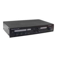
Wall Panel configuration
This section only describes the configuration of the Wall Panel. For information on connecting
and operating the Wall Panel, refer to:
– Wall Panel connections, page 20
– Wall Panel operation , page 40
Figure 7.3: Fig 8-5
Number
Item Description
6 Level control Used to adjust the output level for the Line and Microphone inputs on
the Wall Panel to the All-in-One Unit.
Not
shown
on
drawing
2-pin jumper connector The Wall Panel has an internal 2-pin jumper connector to select
phantom power for the microphone connected to the XLR-connector. To
access the jumper, remove the front control panel as described in Install
Wall Panel, page 13.
– Jumper connected: phantom power ON.
– Jumper removed: phantom power OFF.
7.4
28 en | Configuration Plena All-in-One System
2014.09 | V1.2 | Installation and Operating Manual Bosch Security Systems B.V.
 Loading...
