English–61 619 P03 456 • (05.11) PS
3 FUNCTION
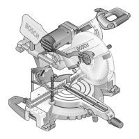
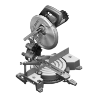
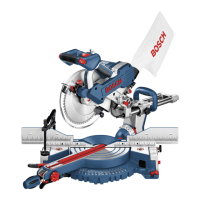
While reading the operating instructions,
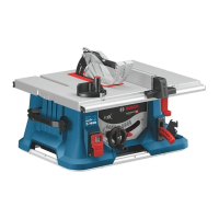
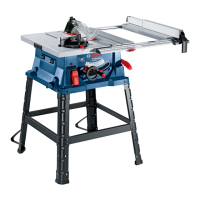
refer to the corresponding illustrations of
the power tool on the front pages.
Intended Use
The power tool is intended as a stationary machine for
making straight lengthways and crossways cuts in
wood.
Horizontal mitre angles of 60° to +60° as well as ver
tical bevel angles of 0° to 45° are possible.
Product Elements
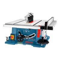
The numbering of the machine elements refers to the
illustrations of the power tool on the front pages of the
operating instructions.
1 Saw table
2 Parallel fence
3 Table insert
4 Riving knife
5 Protective hood
6 Saw blade
7 Guide groove for the angle guide
8 Sticker for marking the cutting line
9 Angle guide for setting the horizontal mitre angle
10 Scale for distance between the saw blade and
parallel fence
11 Front guide groove for the parallel fence
12 Clamping handle for the saw table extension
13 Mounting holes
14 Crank for the raising and lowering of the saw blade
15 Locking lever for setting the vertical bevel angle
16 EMERGENCYOFF button
17 Allen key (5 mm)
18 Vgroove guide for the parallel fence
19 Tool holder
20 Pusher piece
21 Attachment nut for the pusher piece and the tool
holder
22 Auxiliary parallel fence
23 Front Allen screws (5 mm) for adjusting the paral
lelism of the saw blade
24 Groove for the storing of the angle guide
25 Phillips screw for adjusting the 45° stop
26 Stop for 45°
27 Hand wheel
28 Stop for 0°
29 Phillips screw for adjusting the 0° stop
30 Safety flap for the on/off switch
31 Holding clamp for the auxiliary parallel fence
32 Groove for storing the parallel fence
33 Rear Allen screws (5 mm) for adjusting the paral
lelism of the saw blade
34 Cable holder
35 Sawdust ejector
36 Bottom plate
37 Tool well
38 Phillips screw (protective hood attachment)
39 Attachment groove for the riving knife
40 Cutout for table insert
41 Adjustment screws for the table insert
42 Spring clip
43 Vgroove rider of the parallel fence
44 Clamping handle for the parallel fence
45 Wing nut
46 Washer
47 Attachment screw for the auxiliary parallel fence
48 Guide rail of the angle guide
49 Profile for widening the angle guide
50 Attachment set
51 Ring spanner (23 mm)
52 Spindle lock
53 Clamping flange
54 Nut for saw blade attachment
55 Tool spindle
56 Sliding saw table extension
57 Locking knob for the horizontal mitre angle
58 Stop screw for the standard horizontal mitre angle
59 Metal stop for the horizontal standard mitre angles
60 Angle indicator (horizontal)
61 Angle indicator (vertical)
62 Distance indicator, parallel fence
63 Distance indicator, saw table
64 On switch (I)
65 Off switch (O)
66 Knurled nut of the angle guide profile
67 Marked cutting line
68 Side protector
69 Scale for the bevel angle (vertical)
70 Screw of the angle indicator (vertical)
71 Screw for the distance indicator, parallel fence
72 Screw for the distance indicator, saw table
73 Nut of the stop screw for the horizontal standard
mitre angle
Not all the accessories illustrated or described are in>
cluded in standard delivery.
GTS10_WEU.book Seite 6 Mittwoch, 2. November 2005 2:05 14
 Loading...


