English–81 619 P03 456 • (05.11) PS
4 MOUNTING
Avoid unintentional starting of the power
tool. During mounting and for all work on
the power tool itself, the main plug must
not be connected to the power source.
Items Included
Before putting the electrotool into operation, check
that all of the items listed below have been delivered:
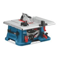
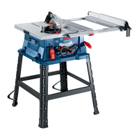
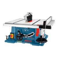
– Table saw with mounted saw blade 6
– Tool holder 19 with Allen key (5 mm) and a ring
spanner (23 mm)
– Bottom plate 36
– 7 Philips head screws for mounting the bottom
plate
–Angle guide 9
–Profile 49
– Attachment set 50 (guide piece, knurled nut,
screw, washer) for the profile 49
– Parallel fence 2
– Auxiliary parallel fence 22 with attachment screws
47, washers 46 and wing nuts 45
– Protective hood 5
–Table insert 3
– Pusher piece 20
Check the power tool for possible damage.
Before further use of the power tool, check that all the
protective devices are fully functional. Any lightly dam
aged parts must be carefully checked to ensure flaw
less operation of the tool. All parts must be properly
mounted and all conditions fulfilled that ensure fault
less operation.
Damaged protective devices and parts must be imme
diately replaced by an authorised service centre.
Initial Operation
Remove all parts supplied carefully from the packag
ing.
Remove all packing material from the power tool and
the accessories provided.
Take special care that the packing material under the
motor block is removed.
Bottom Plate
(see Figure )
Place the electrotool on the saw table 1.
Place the bottom plate 36 in the intended cutout so
that the mounting holes match the holes in the bottom
plate.
Attach the bottom plate with the Philips head screws
provided.
Protective Hood and Table Insert
Mounting the Protective Hood
(see Figure )
Remove all objects located over the tool well 37.
Turn the crank 14 in the clockwise direction to the
stop. The saw blade is raised to the working posi>
tion.
Loosen the screw 38 with a commercially available
Phillips screwdriver. Do not completely remove the
screw.
Slide the groove 39 of the riving knife 4 over the screw
38.
Retighten the screw 38.
The riving knife must be aligned with the saw blade 6
to prevent jamming of the work piece.
Mounting the Table Insert
(see Figure )
To prevent injuries while mounting the table insert, turn
the crank 14 in the counter clockwise direction to the
stop. The saw blade is lowered to the transport po>
sition.
Hook the table insert 3 into the cutout 40 provided in
the tool well 37.
Lower the table insert into the cutout.
Press on the table insert until the spring clip 42 at the
front latches in the tool well.
The front end of the table insert must be flush or just
below the table surface, the rear end flush or slightly
above the table surface.
To set to the correct level, use the four adjustment
screws 41.
Parallel Fence and Angle Guide
Instruction for handling, adjusting and positioning of
the parallel fence and angle guide on the saw table can
be found in the Section "Operating Instructions".
Mounting the Parallel Fence
(see Figure )
Loosen the clamping handle 44 of the parallel fence 2.
This relieves the load on the Vgroove rider 43.
First, place the groove rider of the parallel fence in the
guide groove 18 of the saw table.
Then insert the parallel fence into the front guide
groove 11 of the saw table.
The parallel fence can then be slid to any position. To
lock the parallel fence, press down the clamping han
dle 44.
A
B
C
D
GTS10_WEU.book Seite 8 Mittwoch, 2. November 2005 2:05 14
 Loading...


