English–101 619 P03 456 • (05.11) PS
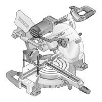
Extending the Saw Table
Before all work on the machine, pull the mains
plug.
Long work pieces must be supported at the free end.
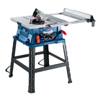
Saw Table Extension
(see Figure
)
Pull the clamping handle 12 upward.
Pull out the saw table extension 56 to the required
length (also see Section "Parallel Fence Adjustment
with Extended Saw Table").
Press the clamping handle 12 downward. The saw ta
ble extension is clamped in this position.
Adjusting the Mitre and
Bevel Angles
Before all work on the machine, pull the mains
plug.
To ensure precise cuts, the basic adjustments of the
power tool must be checked and adjusted as neces
sary after intensive use (see Section "Checking and
Adjusting Basic Adjustment").
Variable Horizontal Mitre Angle
The horizontal mitre angle can be set in the range from
60° (left side) to 60° (right side).
Loosen the locking knob 57 in case it is tightened.
Swing out the metal stop 59. (see Figure
)
Turn the angle guide until the angle indicator 60 points
to the required angle.
Retighten the locking knob 57 .
Standard Horizontal Mitre Angles
(see Figure
)
For quick and precise setting of often used mitre an
gles, stop screws are provided on the angle guide 9 for
the angles of +45° (left and right sides) and 0°.
Loosen the locking knob 57 in case it is tightened.
Swing out the metal stop 59.
Turn the angle guide so that the threads of the re
quired stop screw 58 are on the right of the metal stop.
Swing in the metal stop 59 and turn the angle guide
until the threads of the stop screw rest against the
metal stop.
Retighten the locking knob 57 .
Vertical Bevel Angle
(see Figure )
The vertical bevel angle can be set in the range of 0°
to 45°. For quick and precise setting of often used
bevel angles, stops are provided at angles of 0° and
45°.
Turn the locking lever 15 in the counter clockwise di
rection.
Caution! When loosening the locking lever, the saw
blade tilts as a result of gravity to an angle of approxi
mately 30°.
Pull or push the hand wheel 27 until the angle indicator
61 points to the required bevel angle.
Hold the hand wheel in this position and tighten the
locking lever 15.
Parallel Fence Adjustment
The parallel fence can be positioned to the left (black
scale) or the right (white scale) of the saw blade. The
distance indicator 62 shows through a magnifying
glass the distance set from the parallel fence to the
saw blade.
Position the parallel fence on the required side of the
saw blades (see also Section "Mounting the Parallel
Fence").
With the Saw Table not Extended
Loosen the clamping handle 44 of the parallel fence
and slide it until the distance indicator 62 points to the
required distance to the saw blade (with the saw table
not extended, the lower inscription of the white scale
10 applies).
To clamp in this position, press the clamping handle
44 back down.
With the Saw Table Extended
(see Figure )
Loosen the clamping handle 44 of the parallel fence
and slide it until the distance indicator 62 shows 33 cm
to the saw blade.
Pull the clamping handle 12 upward.
Pull the saw table extension 56 out until the distance
indicator 63 shows the required distance to the saw
blade.
Press the clamping handle 12 downward. The saw ta
ble extension is clamped in this position.
J
K
K
L
M
GTS10_WEU.book Seite 10 Mittwoch, 2. November 2005 2:05 14
 Loading...


