BoschRexrothAG, RE91405-01-B/2021-05-21
34/52 A2FO series 70 | Installation
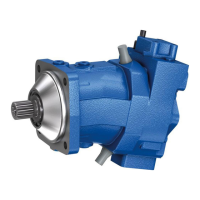
B
T
2
R
S
T
1
Fig� 11: Port overview A2FO, clockwise rotation
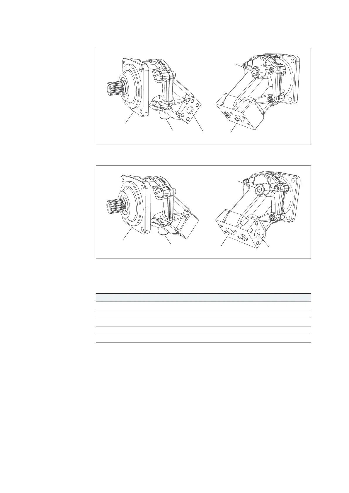
A
T
2
R
S
T
1
Fig� 12: Port overview A2FO, counter-clockwise rotation
Table 10: Ports A2FO series 70
Ports
1)
p
max
[bar]
2)
State
3)
A, B Working port 450 O
S Suction port 30 O
T
1
Drain port 3 X
4)
T
2
Drain port 3 O
4)
R Air bleed port 3 X
1)
The measuring system and thread size can be found in the installation drawing.
2)
Depending on the application, momentary pressure peaks can occur. Keep this inmind when
selecting measuring devices and fittings.
3)
O = Must be connected (comes plugged)
X = Plugged (in normal operation)
4)
Depending on the installation position, T
1
or T
2
must be connected (see chapter 7.3
"Installation position" on page 26)
The following tightening torques apply:
• Fittings:
Observe the manufacturer's specifications regarding the tightening torques of the
fittings used.
• Female threads in the axial piston unit:
The max. permissible tightening torques M
G max
are the maximum values for the
female threads and should not be exceeded. For values, see Table 11.
Port overview
Tightening torques

 Loading...