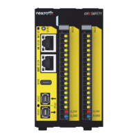
4.2.5 Overall connection diagram XCD
XD01 Mains
XD02 DC bus
XD04 Internal/external braking resistor
XD10 Control voltage
XF21, XF22 Communication
XG02 Ready for operation relay contact
XG20 Digital encoder
XG21 Multi-encoder (optional)
XG31 Digital inputs/outputs; analog input
XG4x Safety technology
XZ03 Motor, motor temperature monitoring, motor holding brake
Fig. 4-4: Overall connection diagram XCD
Symbols: See chapter 4.2.14 "Symbols (connection diagram)" on page 36
ctrlX DRIVE Drive Controllers, Supply Units 27/43
Instructions for use
R911392530_Edition 02 Bosch Rexroth AG
 Loading...


