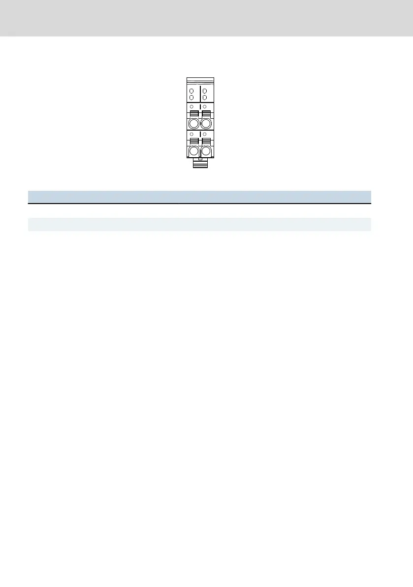
Power connector XD1
Fig. 10-9: Power connector XD1
Connector contact Signal Function
a1, a2 U
L
+24 V +24 V DC supply voltage (U
L
)
b1, b2 GND GND (U
L
) (ground supply voltage)
Tab. 10-1: Pin assignment of the power connector XD1
10.5.3 24 V voltage supply
The voltage of 24 V can be supplied with or without electrical isolation. The CAN
extension module is provided with a GND/FE separation. The other extension
modules are provided with a low-ohmic GND/FE connection.
11
Commissioning
The extension modules can be directly operated. Programming or configuration
is not required.
Observe the operating instructions of the control, see chapter 1.3 "Related
documents" on page 2.
When commissioning the extension module "CAN", the internal, programmable
function block is loaded. After successful loading, the LED "ON" is green at the
voltage plug. Then, the internal, programmable function blocks of the control
"XMxx" are loaded. If these function block have been loaded successfully as
well, the display "ON" is green at the voltage supply plug of the control "XMxx".
In case of an error, the display LED is not on, refer to chapter 13 "Error causes
and troubleshooting" on page 26.
12
Device description
Use the extension modules "Sercos", "Profibus", "Profinet" and "CAN" for a field
bus with the same name at a control.
Bosch Rexroth AG
Device description
Extension Modules Profibus, RT-
Ethernet, Sercos, CAN
24/37
DOK-CONTRL-XFE**EXTMOD-IT04-EN-P

 Loading...


