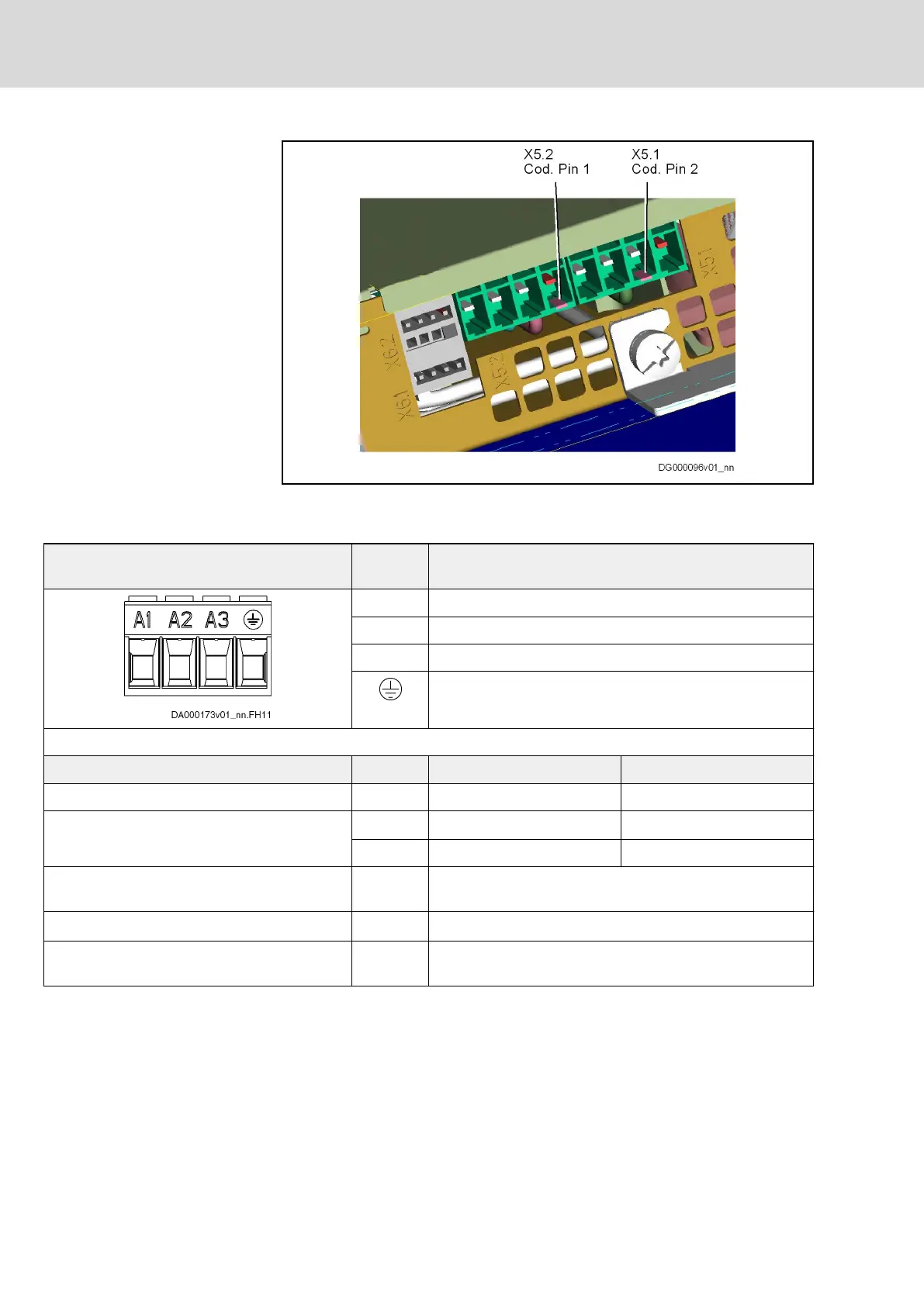
Fig.5-3: Coding of X5.1 and X5.2
Connection Point
View Identifica‐
tion
Function
A1 For power connection U1 at motor
A2 For power connection V1 at motor
A3 For power connection W1 at motor
For equipment grounding conductor of motor
Screw connection at connector Unit Min. Max.
Tightening torque Nm 0,5 0,6
Connection cable
Stranded wire
mm
2
1,0 4
AWG 18 10
Occurring current load and minimum required
connection cross section
A See technical data of device used (I
out
)
Occurring voltage load V See technical data of device used (U
out
)
Short circuit protection A1, A2, A3 against each other and each of them against
ground
Fig.5-4: Function, Pin Assignment, Properties
Bosch Rexroth AG DOK-INDRV*-HMD01******-IT01-EN-P
Rexroth IndraDrive Drive Controllers Power Sections HMD01
32/67
Instructions for Use
Courtesy of CMA/Flodyne/Hydradyne ▪ Motion Control ▪ Hydraulic ▪ Pneumatic ▪ Electrical ▪ Mechanical ▪ (800) 426-5480 ▪ www.cmafh.com




 To Next Page