● Maximum
allowed inductance of 100 µH (2 twisted single strands, 75 m
long)
● Parallel line routing where possible
The input 0V is connected in conductive form to the housing po‐
tential.
It is therefore impossible to use an insulation monitor at
+24V and 0V against housing.
5.2.6 L+ L-, DC Bus Connection
Lethal electric shock by live parts with more
than 50 V!
Before working on live parts: De-energize installation and secure power
switch against unintentional or unauthorized re-energization.
Wait
at least 30 minutes after switching off the supply voltages to allow dis‐
charging.
Check whether voltage has fallen below 50 V before touching live parts!
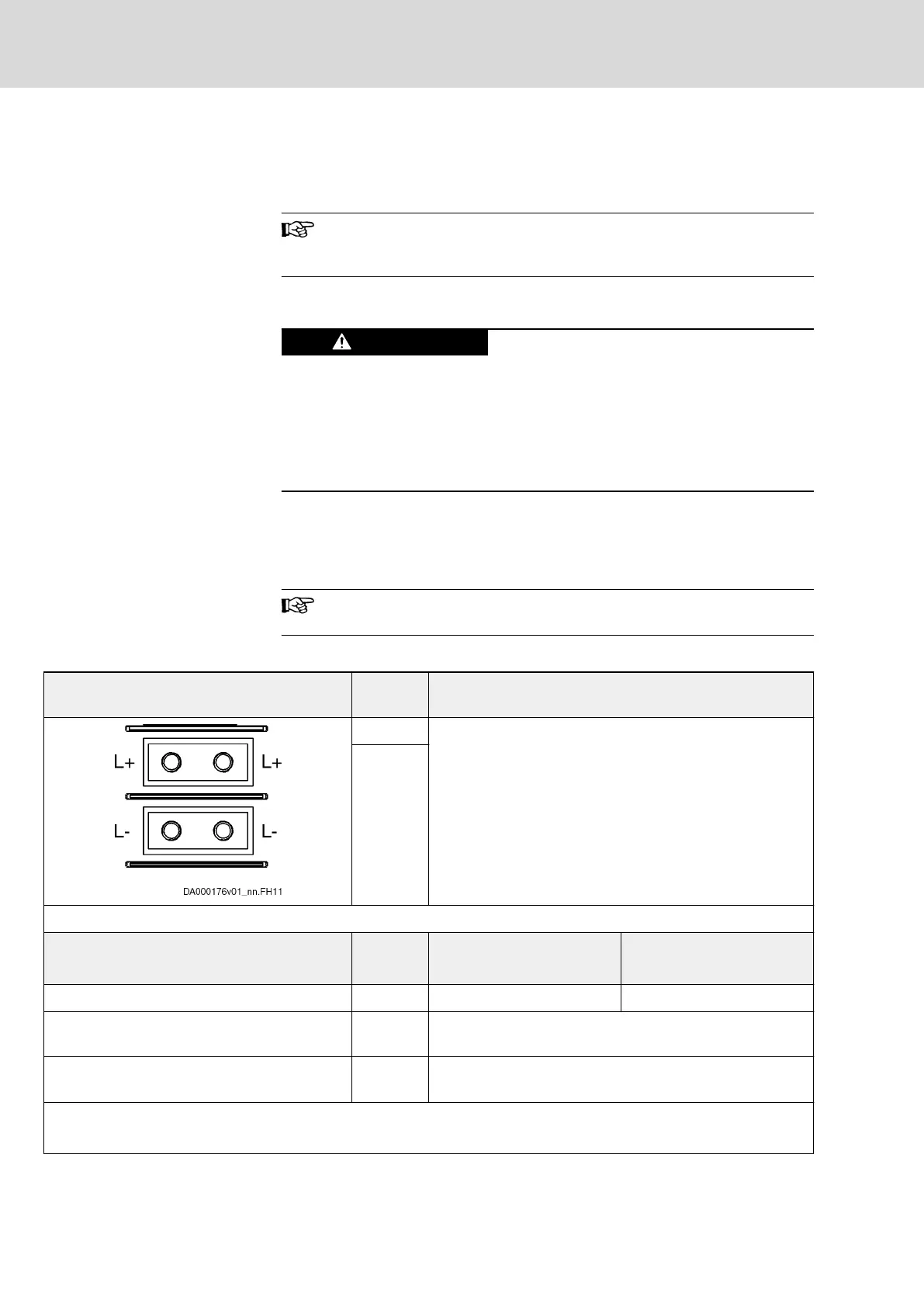
Function, Pin Assignment
The DC bus connection connects
●
several drive controllers to one another
● a drive controller to additional components
HCS02.1E-W0012 drive controllers do not have a DC bus con‐
nection.
Technical Data of the Connection Point
View Identifica‐
tion
Function
L+ Connection points for connecting DC bus connections
L-
Screw connection
M6 thread at device (terminal block)
Unit Min. Max.
Tightening torque Nm 5,5 6,5
Short circuit protection Via fusing elements connected in the incoming circuit to the
mains connection
Overload protection Via fusing elements connected in the incoming circuit to the
mains connection
Current carrying capacity "looping through"
from L+ to L+, L- to L-
(contact bars in scope of supply of accessory HAS01)
Bosch Rexroth AG DOK-INDRV*-HMD01******-IT01-EN-P
Rexroth IndraDrive Drive Controllers Power Sections HMD01
38/67
Instructions for Use
Courtesy of CMA/Flodyne/Hydradyne ▪ Motion Control ▪ Hydraulic ▪ Pneumatic ▪ Electrical ▪ Mechanical ▪ (800) 426-5480 ▪ www.cmafh.com




 To Next Page