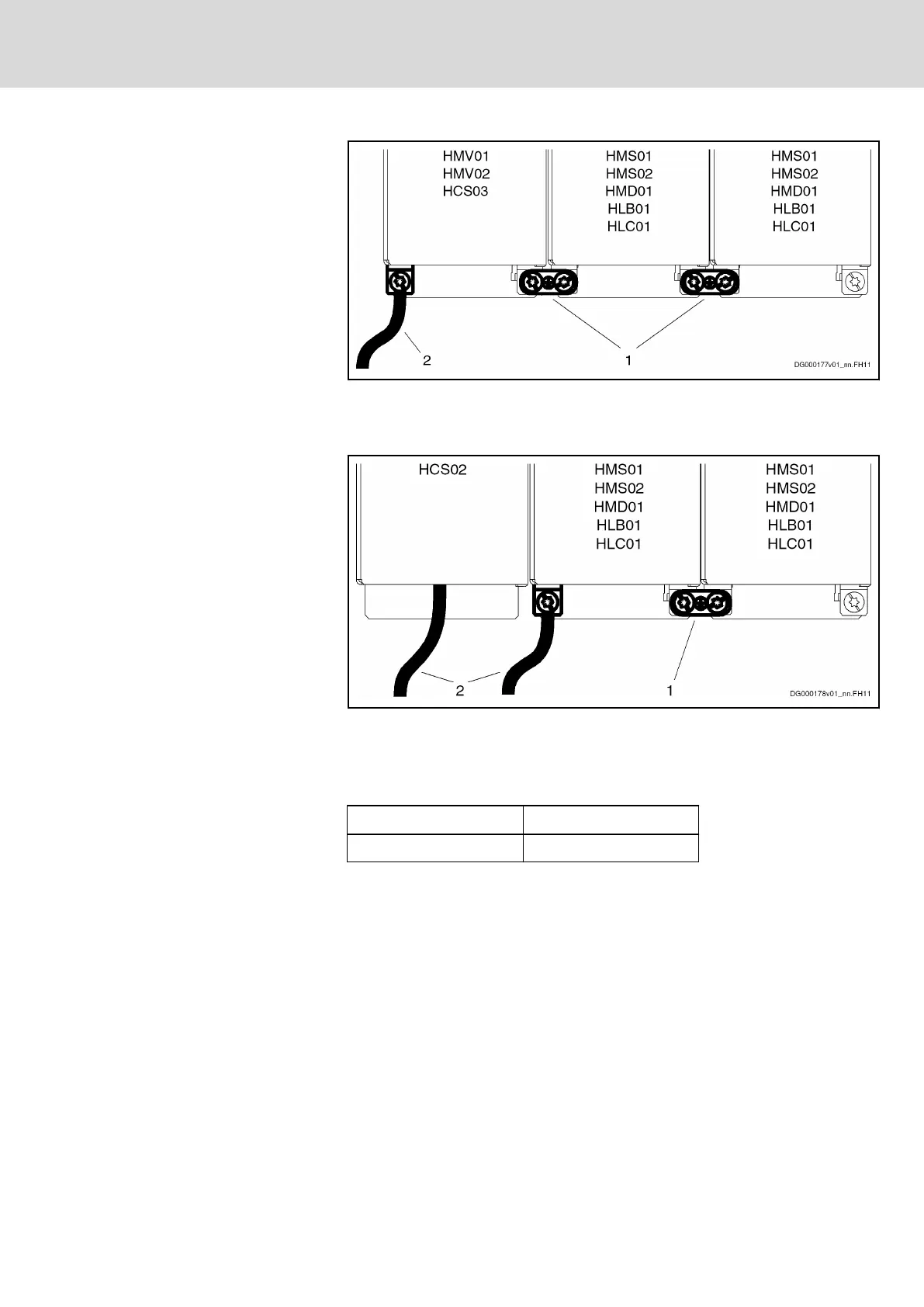
1 Joint bar
2
Connection to equipment grounding system
Fig.5-15: Equipment Grounding Conductor Connection for Supply via HMV01,
HMV02, HCS03
1 Joint bar
2
Connection to equipment grounding system
Fig.5-16: Equipment Grounding Conductor Connection for Supply via HCS02
Design, Tightening Torque
The joint bars are connected by means of screws:
Design Tightening torque
M6 × 25 6 Nm
Fig.5-17: Data of Connection Point
5.2.8 Ground Connection
The ground connection of the housing is used to provide functional safety of
the drive controllers and protection against contact in conjunction with the
equipment grounding conductor.
Ground the housings of the drive controllers:
1. Connect the bare metal back panel of the drive controller in conductive
form to the mounting surface in the control cabinet. To do this, use the
supplied mounting screws.
2. Connect the mounting surface of the control cabinet in conductive form
to the equipment grounding system.
3. For the ground connection, observe the maximum allowed ground re‐
sistance.
DOK-INDRV*-HMD01******-IT01-EN-P
Rexroth IndraDrive Drive Controllers Power Sections HMD01
Bosch Rexroth AG 41/67
Instructions for Use
Courtesy of CMA/Flodyne/Hydradyne ▪ Motion Control ▪ Hydraulic ▪ Pneumatic ▪ Electrical ▪ Mechanical ▪ (800) 426-5480 ▪ www.cmafh.com




 To Next Page