Short circuit protection X6.3 against X6.4 (output for controlling the motor holding
brake)
Overload protection X6.3 against X6.4 (output for controlling the motor holding
brake)
1) Maximum time constant of load: t = R
Br
/ L
Br
(R
Br
= resistance of brake;
L
Br
= inductance of brake)
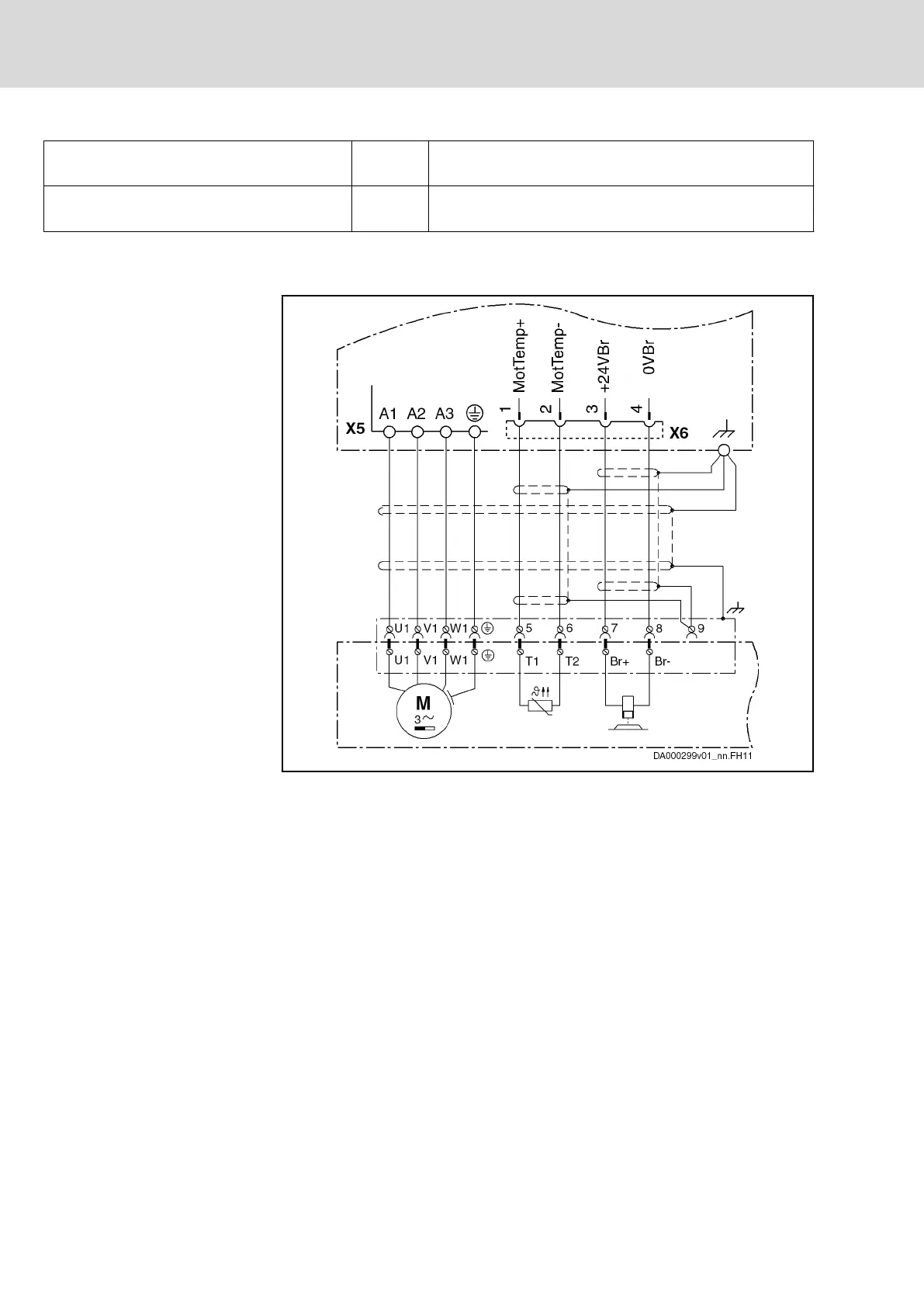
Fig.5-7: Function, Pin Assignment
Connection Diagram
The connection of the equipment grounding conductor can either be at
terminal connector X5 or directly at the drive controller (this figure
shows a terminal connector X5 with connection of the equipment
grounding conductor).
Fig.5-8: Connection of Motor Temperature Monitoring and Motor Holding
Brake
5.2.5 Terminal Block, 24V - 0V (24V Supply)
Function, Pin Assignment
Connection of external 24V supply:
24V supply of HMS, HMD, HCS power sections (not at HCS02)
● For the power section of the drive controller
● For brake control via X6
● For the control section of the drive controller with the optional modules,
except for such optional modules (e.g. safety technology S1) which re‐
quire their own power supply
Bosch Rexroth AG DOK-INDRV*-HMD01******-IT01-EN-P
Rexroth IndraDrive Drive Controllers Power Sections HMD01
36/67
Instructions for Use
Courtesy of CMA/Flodyne/Hydradyne ▪ Motion Control ▪ Hydraulic ▪ Pneumatic ▪ Electrical ▪ Mechanical ▪ (800) 426-5480 ▪ www.cmafh.com




 To Next Page