With contact bars -072 A 220
Additionally with contact bars ‑042 and end
piece
A 245
Fig.5-11: Function, Pin Assignment, Properties
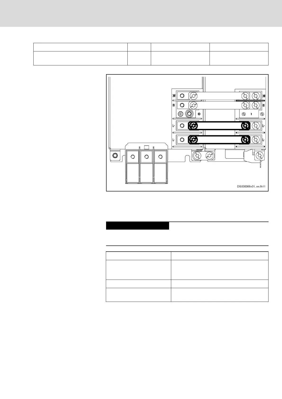
Fig.5-12: DC Bus Connection With Contact Bars
Notes on Installation
If in special cases it is not possible to use the contact bars provided to estab‐
lish the connection, the connection must be established using the shortest
possible twisted wires.
Risk of damage by reversing the polarity of
the DC bus connections L+ and L-
Make sure the polarity is correct.
Length of twisted wire Max. 2 m
Line cross section
Min. 10 mm
2
,
but not smaller than cross section of supply feed‐
er
Line protection By means of fuses in the mains connection
Dielectric strength of single
strand against ground
≥ 750 V (e.g.: strand type – H07)
Fig.5-13: DC Bus Line
DOK-INDRV*-HMD01******-IT01-EN-P
Rexroth IndraDrive Drive Controllers Power Sections HMD01
Bosch Rexroth AG 39/67
Instructions for Use
Courtesy of CMA/Flodyne/Hydradyne ▪ Motion Control ▪ Hydraulic ▪ Pneumatic ▪ Electrical ▪ Mechanical ▪ (800) 426-5480 ▪ www.cmafh.com




 To Next Page