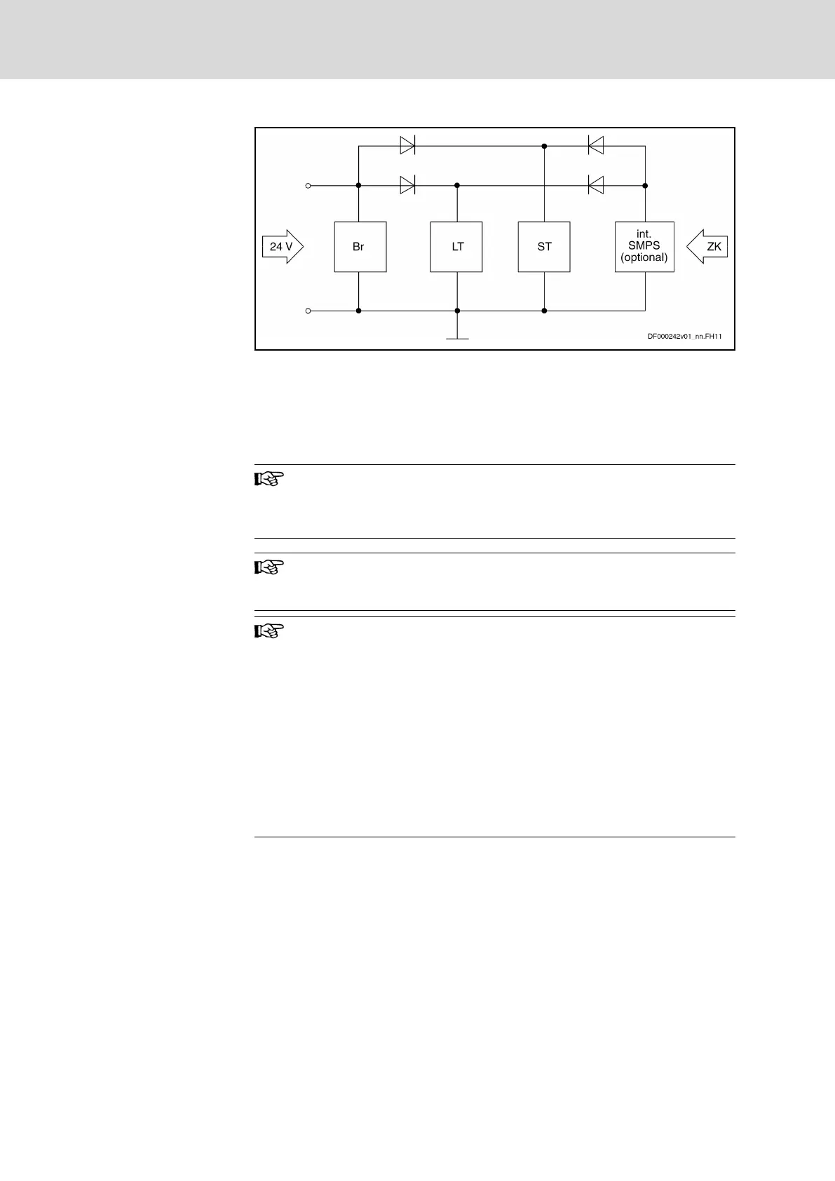
BR Circuit for brake control
LT Power section, e.g. HCS02
ST Control section, e.g. CSB01
int. SMPS For types HCS0x.1E-Wxxxx-NxxV: Internal switched-mode power
supply
ZK DC bus
Fig.5-5: Block Diagram of Internal Control Voltage
Notes on Installation
Make sure the voltage supply for the motor holding at the motor
brake is sufficient. You have to take into account that voltage
drops on the supply line. Use connecting lines with the highest
possible cross section of the single strands.
An external contact element is required, if motor holding brakes
with higher currents than the allowed current load are to be sup‐
plied at X6.
Coding of the Connectors
At the HMD power sections with two inverter outputs, the outputs
have been coded, i.e. provided with a coding section. This avoids
accidentally interchanging the two cables.
Coding
● X6.1: Coding section at pin 4
● X6.2: Coding section at pin 1
For ready-made Rexroth motor power cables, you therefore have
to code the male connector at the motor power cable accordingly
for X6.1 and X6.2:
● For connector X6.1: Cut off plastic pin 4 at connector
● For connector X6.2: Cut off plastic pin 1 at connector
Bosch Rexroth AG DOK-INDRV*-HMD01******-IT01-EN-P
Rexroth IndraDrive Drive Controllers Power Sections HMD01
34/67
Instructions for Use
Courtesy of CMA/Flodyne/Hydradyne ▪ Motion Control ▪ Hydraulic ▪ Pneumatic ▪ Electrical ▪ Mechanical ▪ (800) 426-5480 ▪ www.cmafh.com




 To Next Page