RF Unit Installation
5.11 Electrical—Low-Voltage Wiring
For heat pumps with a constant-airflow fan motor, the
thermostat wiring is connected to a terminal strip located on the
ECM (Electronically Commutated Motor) control board, which is
located in the electrical box. Refer to the unit wiring diagram for
connection details.
WARNING
Never route control wiring through the same conduit as power
supply wiring.
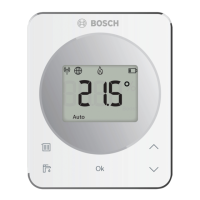
5.11.1 Thermostat
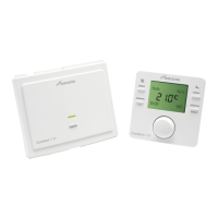
Unless provided with DDC controls, the RF heat pump can be
controlled by most commonly avai
lable single-stage or
two-stage heat pump thermostats, depending on model.
The reversing valve on the RF series is energized when the unit is
in cooling mode. Position ther
mostats on an interior wall away
from supply ducts.
Avoid external walls and locations subject to direct sunlight and
drafts. Thermostat wiring must b
e 18AWG (American Wire
Gauge). Refer to the installation instructions of the thermostats
for further details.
NOTICE
To prevent voltage drops in the control circuit, do not exceed
the recommended thermostat wire lengths detailed in
Table 7.
Connection Function
Y1 First-Stage Compressor Operation
Y2 Second-Stage Compressor Operation
G Fan
O Reversing Valve (energized in cooling)
W1
Auxiliary Electric Heat (runs in conjunction with
compressor)
EM/W2 Emergency Heat (electric heat only)
NC
Transformer 24 VAC Common (extra
Table 5 Unit Thermostat Connections
5.11.2 VA Capacity
The VA capacity of the transformer must be considered when
connecting low-voltage access
ories to the heat pump such as
thermostats or solenoid valves. Table 6 shows the VA draw of
factory-mounted components in the low-voltage heat pump. The
total VA draw of the heat pump inte
rnal components plus
attached accessories must be lower than the VA capacity of the
unit control transformer.
WARNING
Exceeding the transformer capacity will result in low control
voltage, erratic unit operation, or damage to the heat pump
connection)
C1
Transformer 24 VAC Common (primary
connection)
R Transformer 24 VAC Hot
H Dehumidification Mode
Standard Construction
Component VA
Reversing Valve Solenoid 12
Compressor Contactor Single Phase 10
UPM Board 5
Total VA Draw 27
Table 6 Low-Voltage VA Draw —Standard Construction, Hot Gas
Reheat or Economizer, and Optional Components
5.11.3 Thermostat to HVAC Equipment Wiring
The thermostat may not function properly if the total resistance
of any of the thermostat to HVAC equ
ipment wires exceeds 2.5
ohms. To ensure that wire length does not cause excess
resistance, refer to Table 7 and ensure that the wires from the
thermostat to the HVAC equipment are not too long.
Copper Wire Gauge Maximum Wire Length
22 AWG (0,33mm
2
)
150 ft. (46m)
20 AWG (0,50mm
2
)
240 ft. (73m)
18 AWG (0,75mm
2
)
385 ft. (117m)
Table 7 Length by Wire Gauge for Thermostat to HVAC Equipment
Wiring
20 |
RF Series Heat Pumps — 8733980022 (2024/12)








 To Next Page