Dimensional Drawings
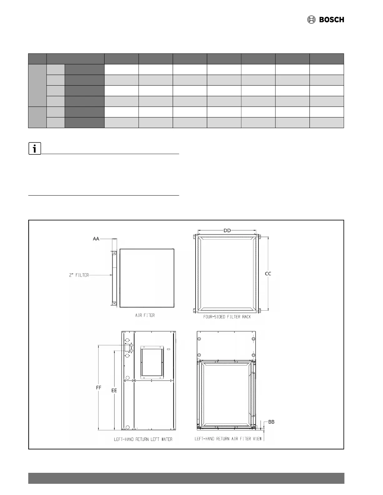
22.6 Counter Flow Options Dimensions
Table 28 Counter Flow Options Dimensions
Model RF024 RF030 RF036 RF042 RF048 RF060 RF070
Filter Racks
AA
2" Filter Rack
2.25” 2.25” 2.25” 2.25” 2.25” 2.25” 2.25”
BB
Filter Rack Height
0.75” 0.75” 1” 1.25” 1.25” 2” 2”
CC
R/A Duct Flange Height
20” 24.75” 28” 28” 28” 34” 34”
DD
R/A Duct Flange Width
16” 16.25” 22” 22” 22” 27.25” 27.25”
HRP
EE
HRP Inlet
30.25” 30.25” 35.25” 35.25” 35.25” 44” 44”
FF
HRP Outlet
32.75” 32.75” 37.75” 37.75” 37.75” 46.25” 46.25”
• Specifications subject to change without notice.
• All dimensions within ±0.125".
• Filter ra
ck dimensions does not include 1" duct flange.
• 2" filter racks can accept either a 1" or 2" filter.
• HRP Connections are 1/2" FNPT.
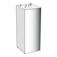
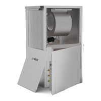
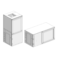
Fig. 35 Counter Flow Options Dimensions Drawing
80 |
RF Series Heat Pumps — 8733980022 (2024/12)