RF Unit Installation
5.12 ECM Interface Board
NOTICE
ECM Interface Boards are used only with the Constant Airflow
motor option.
NOTICE
Do not set the ADJ DIP switch to the (-) setting when electric
heaters are installed. Doing so may cause the heaters to cycle
on their thermal overload switches, potentially shortening the
life of the switches.
Thermostat wiring is connected to the 10-pin screw-type
terminal block on the lower-center portion of the ECM Interface
Board. In addition to providing a connecting point for thermostat
wiring, the interface board also translates thermostat inputs into
control commands for the Electronic Commutated Motor (ECM)
DC fan motor and displays an LED indication of operating status.
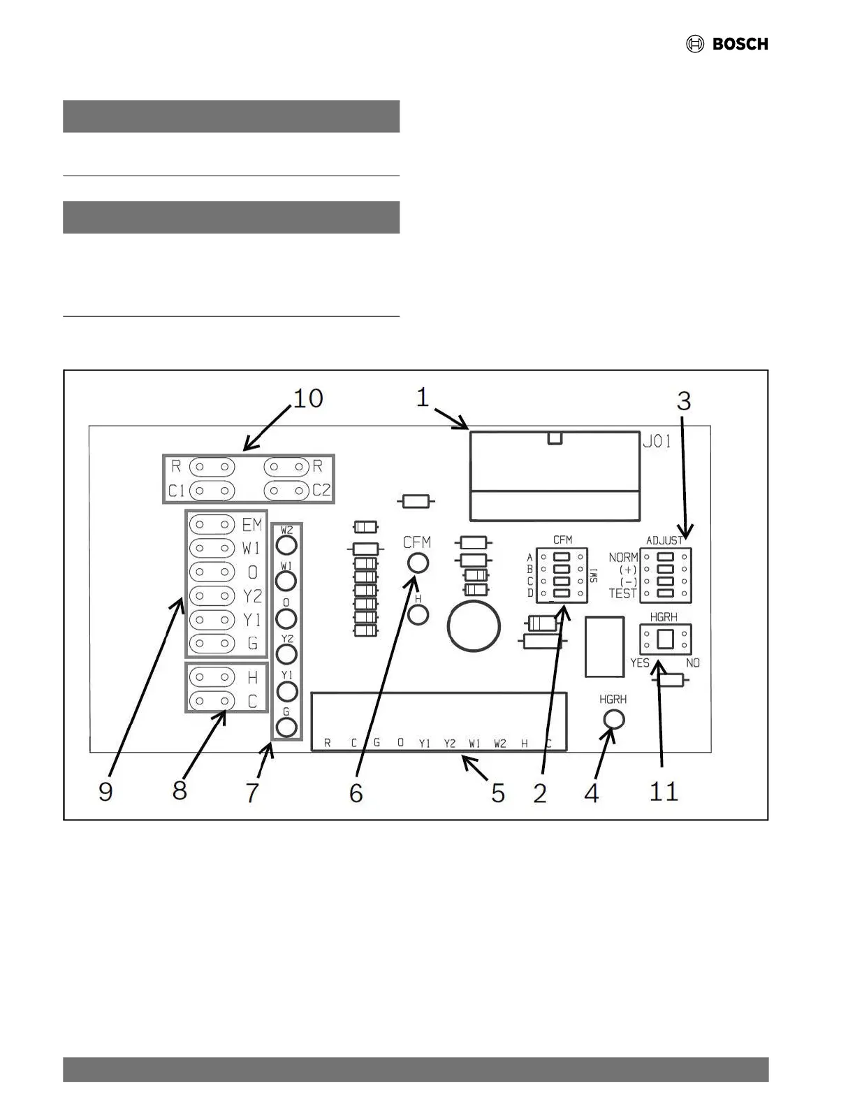
The thermostat connections and their functions are as shown in
Fig. 14.
Fig. 14 ECM Interface Board
[1] Motor Harness Plug
[2] Blower CFM Adjustment
[3] Motor Settings
[4] HGRH Indication
[5] Thermostat Contact Inputs
[6] CFM Count Indicator
[7] Thermostat Input Status Indication
[8] Reheat Digital Outputs
[9] Thermostat Outputs
[10] 24 VAC
[11] Hot Gas Re-Heat Enable Switch
22 |
RF Series Heat Pumps — 8733980022 (2024/12)