12 Safety Devices and the UPM Controller
Overview
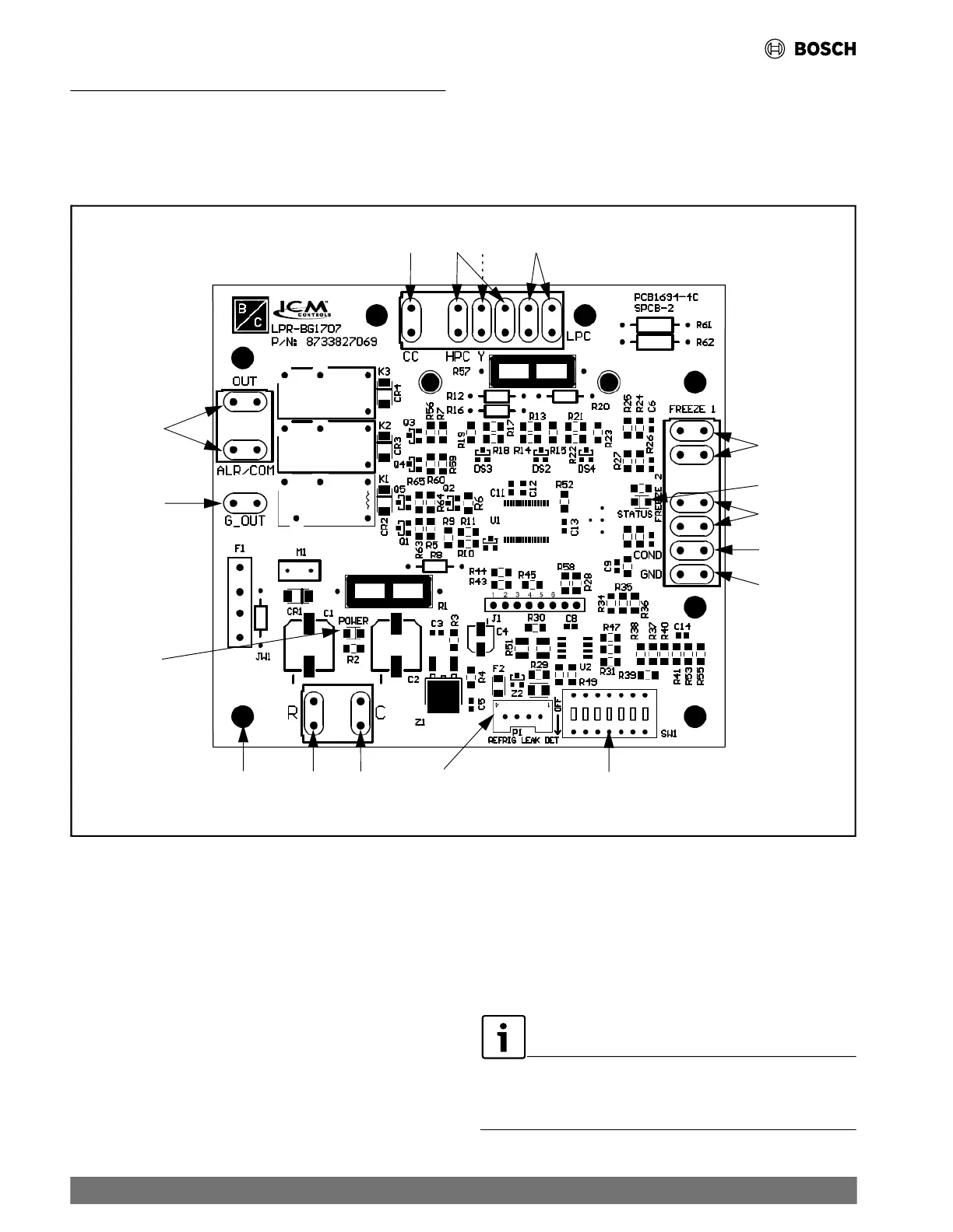
RF models are equipped with the Unit Protection Module (UPM)
that controls the compressor operation and monitors the safety.
Fig. 18 UPM Controller Board
1
2
3
4
5
6
7
8
9
10
11
12
13
14
15
16
17
[1] Compressor Contact Output
[2] High-Pressure Switch Connection
[3] Call for Compressor Input Signal (Y1)
[4] Low-Pressure Switch Connection
[5] Water Coil Freeze Connection (FREEZE 1)
[6] UPM Status LED Indicator (Fault Status)
[7] Air Coil Freeze Connection (FREEZE 2)
[8] Condensate Overflow Sensor Connection
[9] Ground
[10] UPM Settings DIP Switch (SW1)
[11] A2L Sensor
[12] 24VAC Power Common
[13] 24VAC Power Input
[14] UPM Standoff
[15] Power LED
[16] Fan (Fan in the event of an A2L leakage)
[17] Dry Contact
When a malfunction light is used for diagnostic purposes, the
connection is made at the dry contact connection terminals of
the UPM board.
Safety Devices and the UPM Controller Overview
30 |
RF Series Heat Pumps — 8733980022 (2024/12)