Safety Devices and the UPM Controller Overview
12.1 UPM Default Settings and DIP Switch Positions
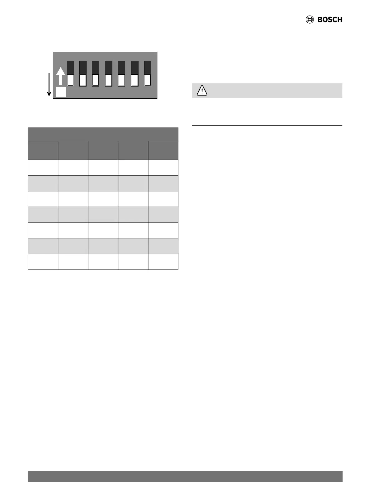
Fig. 21 UPM Settings DIP Switch (SW1)
Table 10 UPM DIP Switch Selectable Positions
UPM DIP Switch Selectable Positions
Position Function ON OFF
Factory
Default
1 Lockout 4 2 2
2 Reset R Y Y
3 Alarm Cont Pulse Pulse
4 Test Yes No No
5 Freeze 1 15°F 25°F 25°F
6 Freeze 2 15°F 25°F 25°F
7 Pump ON OFF OFF
12.2 UPM Board Features
The UPM Board includes the following features:
• ANTI-SHORT CYCLE TIMER: Five-minute delay on
break timer to prevent compressor short cycling.
• COMPRESSOR MINIMUM RUN TIME: The UPM
has a minimum compressor run time of five minutes. If Y-call
is removed the compressor will remain energized until the
five minutes have expired.
• RANDOM START: Each controller has an unique random
start delay ranging from 270 to 300 seconds on initial power
up to reduce the chance of multiple unit simultaneously
starting at the same time after power up or after a power
interruption, in order to avoid creating a large electrical
spike.
• TEST DIP SWITCH: The DIP switch position “4” controls
the Test function. When it is set to “ON,” it will reduce all time
delays settings to 10 seconds during troubleshooting or
verification of unit operation. (
Refer to Fig. 18, item [10].)
(
Refer to Fig. 21.)(See Table 10.)
CAUTION
Operation of the unit in test mode can lead to accelerated
wear and premature failure of components. The "TEST" switch
must be set back to "OFF" after troubleshooting/servicing.
• LOW-PRESSURE BYPASS TIMER: If the
compressor is running and the low-pressure switch opens,
the controller will keep the compressor ON for 120 seconds.
After two minutes if the low-pressure switch remains open,
the controllers will shut down the compressor and enter a
soft lockout. The compressor will not be energized until the
low-pressure switch closes and the anti-short cycle time
delay expires. If the low-pressure switch opens two or four
times in one hour, the unit will enter a hard lockout. In order
to exit a hard lockout, power to the unit would need to be
reset. The reset signal is either a Y or R signal depending on if
DIP switch position “2” is set to ON or OFF. (
Refer to Fig.
21.)(See Table 10.) If it set to ON, the board must be
manually powered OFF and powered back ON to exit the hard
lock out.
• BROWNOUT/SURGE/POWER INTERRUPTION
PROTECTION: The brownout protection in the UPM
board will shut down the compressor if the incoming power
falls below 18 VAC. The compressor will remain OFF until the
voltage is above 18 VAC and ANTI-SHORT CYCLE TIMER
(300 seconds) times out. The unit will not go into a hard
lockout.
• MALFUNCTION OUTPUT: Alarm output is Normally
Open (NO) dry contact. If pulse is selected the alarm output
will be pulsed. The fault output will depend on the DIP switch
setting for "ALARM." (
Refer to Fig. 21.)(See Table 10.)
If DIP switch position “3” is set to “ON,” a constant signal will
be produced to indicate a fault has occurred and the unit
requires inspection to determine the type of fault. If it is set to
“OFF," a pulse signal is produced and a fault code is detected
by a remote device indicating the fault. (For blink code
explanation, see Table 11.) The remote device must have a
malfunction detection capability when the UPM board is set
to "PULSE."
32 |
RF Series Heat Pumps — 8733980022 (2024/12)