9
Bosch Security Systems 09/06 BLCC100R
Solution 16
plus
Quick Start Guide
Te rmina l Des cript ions
Nº Name Description
1 Earth
Earth wire from this terminal is connected
to the Mains earth.
2
3
~ (AC)
~ (AC)
Connection of the A.C. plug pack
transformer
4
5
BAT (-)
BAT (+)
Negative and positive connections to the
stand-by battery. 12 VDC / 7AH
6
7
8
9
10
11
+12 V
+12 V
+12 V
GND
GND
GND
These terminals are used to power
detectors and LAN devices up to 750
mA.
12
13
LAN +
LAN -
These terminals are used to power LAN
devices up to 750 mA.
14 LAN A
Connect the LAN A data terminal of any
LAN device (eg. Keypads, expansion
boards) to this terminal. The control
panel supports up to 300 m of 24/0.20
(18 AWG) wire on these terminals.
15 LAN B
Connect the LAN B data terminal of any
LAN device (eg. Keypads, expansion
boards) to this terminal. The control
panel supports up to 300 m of 24/0.20
(18 AWG) wire on these terminals.
16 COMM+
Alarm power capable of providing a
maximum of 2 Amp (+). This terminal is
PTC Fuse protected.
17
18
19
OUT 1
OUT 2
OUT 3
Programmable output, capable of
providing a maximum of 500 mA (-). This
terminal is PTC Fuse protected.
20
21
22
N/C
COM
N/O
2 A @ 24 VDC Relay Output -
Form C contact
23 INPUT
Programmable Input for RF Receivers,
Keyswitch and other devices.
24 ZN 1 Zone 1 and 9 sensor loop input (+).
25 GND
Common (-) for Zone 1 and 2 sensor
loop.
26 ZN 2 Zone 2 and 10 sensor loop input (+).
27 ZN 3 Zone 3 and 11 sensor loop input (+).
28 GND
Common (-) for Zone 3 and 4 sensor
loop.
29 ZN 4 Zone 4 and 12 sensor loop input (+).
30 ZN 5 Zone 5 and 13 sensor loop input (+).
31 GND
Common (-) for Zone 5 and 6 sensor
loop.
Nº Name Description
32 ZN 6 Zone 6 and 14 sensor loop input (+).
33 ZN 7 Zone 7 and 15 sensor loop input (+).
34 GND
Common (-) for Zone 7 and 8 sensor
loop.
35 ZN 8 Zone 8 and 16 sensor loop input (+).
36
37
IN
IN
These terminals are used to connect the
telephone line from the street.
38
39
OUT
OUT
These terminals are used to connect the
premises telephones.
Table 4: Terminal Block Descriptions
Bo ard Conne cto rs
Connector Description
Service
This socket allow you to connect a service
Keypad to the panel during installation.
Tamper
This socket is used to connect the panel
enclosure tamper switch.
Default
This push button is used to reset the con
-
trol panel back to factory default.
Voice
Module
This is used to connect the optional Voice
Command Module (CM100).
Serial
This socket is used to connect serial devic
-
es to the control system like the direct link
programming module.
Telco
This is a RJ12 6P/4C connector that allows
you to connect the control panel to the
PSTN telephone line.
Relay
The relay select PIN’s allow you to eas
-
ily program the relay common contact to
switch either +12v or GND by fitting a plug
on link.
Table 5: Board Connector Descriptions
About The Key pad
The Graphic Keypad has 20 keys or buttons. The buttons
allow you to input instructions and navigate the menu
screens as required. Some buttons have a secondary
function which is activated by holding them down for two
seconds. Each button’s function is described below
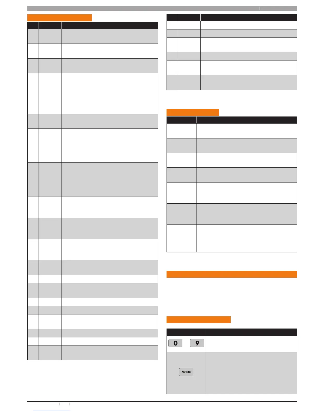
Key pad Key Fun ctio ns
Key Description
to
The numeric keys allow you to enter
you numbers when required
Use the [MENU] and the numeric keys
to enter commands. The [MENU] key
is also used to go back one level when
navigating through menus or to exit a
programming location without saving
changes.