23
Bosch Security Systems 09/06 BLCC100R
Solution 16
plus
Quick Start Guide
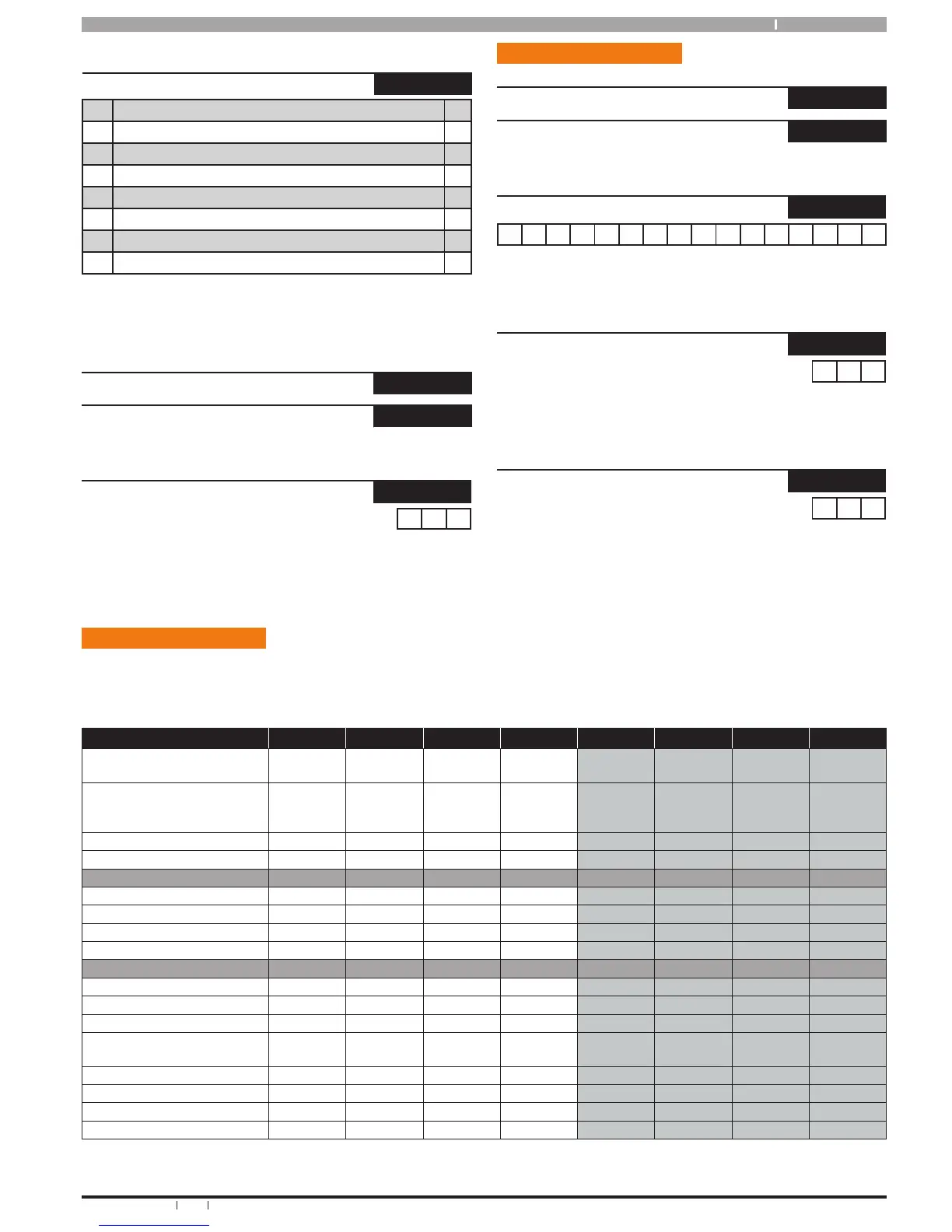
Inputs > Tamper Inputs >
Tamper Options MENU 3-6-0
1 Display Panel Tamper Y
2 Report Panel Tamper Y
3 Audible Panel Tamper Y
4 Display Expander Tamper Y
5 Report Expander Tamper Y
6 Audible Expander Tamper Y
7 Reserved N
8 Reserved N
Use Keys [] and [] to scroll up and down the option list. With option
selected press ON / OFF key to enable or disable option. [] will display
to indicate option set. Press [OK] To Save when finished.
Inputs > Input Testing >
Walk Test All Zones
MENU 3-9-0
Walk Test A Zones
MENU 3-9-1
Inputs > Input Testing >
Sensor Watch Time
MENU 3-9-2
0 3 0
(*** System Wide Parameter ***)
DAYS
Enter 0 – 255 + [OK] To Program The Sensor Watch Time In Days (0 =
Disabled)
Ou tput Prog ram ming
Outputs > Commands >
Output Status
MENU 4-0-0
Turn Output On/Off
MENU 4-0-1
Outputs > Properties >
Output Name
MENU 4-1-0
O u t p u t 1 N a m e
Use [] and [] Keys To Scroll Cursor Left and Right. Use Keys [0] – [9]
+ [] and [] To Toggle Characters + Enter [OK] To Save.
Outputs > Properties >
Event Type
MENU 4-1-1
0 0 0
Use Keys [] and [] keys or enter desired Event type 0 – 255 + [OK].
See Output Event Type table for available options.
Outputs > Properties >
Event Assignment
MENU 4-1-2
0 0 1
Enter 0 to 255 to program the Area, User, Zone, Keypad or Access
Group Number You Want The Output To Follow Then Press [OK].
(0 = Unrestricted all Areas, Users, Zones etc)
Ou tput Defau lt Table
The table below list the default values for all Output parameters in the Solution 16
plus
. Outputs 1 to 3 are High current
digital outputs and Output 4 is the onboard relay output. Outputs 5 to 8 are only available if the optional Output Relay
Expander Boards (CM110) are fitted. Options marked N/A = Not Applicable.
Programming Option Output 1 Output 2 Output 3 Output 4 Output 5 Output 6 Output 7 Output 8
Output Name
External
Siren
Strobe
Light
Smoke
Sensor PWR
Internal
Siren
Output 5
Name
Output 6
Name
Output 7
Name
Output 8
Name
Event Type
36
(External
Siren)
48
(Strobe)
49
(Smoke
Sensor GND)
37
(Internal
Siren)
0 0 0 0
Event Assignment
1 1 1 1 1 1 1 1
Output Polarity
14 6 11 6 0 0 0 0
Time Parameter
N° Of Hours
000 008 000 000 000 000 000 000
N° Of Minutes
005 000 000 005 000 000 000 000
N° Of Seconds
000 000 010 000 000 000 000 000
N° Of 1/10 Seconds
000 000 000 000 000 000 000 000
Output Options
Do not Operate If Low Battery
Y Y Y Y N N N N
Display Output Overload
Y Y Y N/A N/A N/A N/A N/A
Report Output Overload
Y Y Y N/A N/A N/A N/A N/A
Display Missing Output
Device
Y N N N/A N/A N/A N/A N/A
Report Missing Output Device
Y N N N/A N/A N/A N/A N/A
Alarm On Device Fail
N N N N N/A N/A N/A N/A
Block Output If Armed All On
N N N N N N N N
Display Status On Keypad
N N N N N N N N
Table 16: Output Default Table