5
THEORY OF OPERATION
General Overview
The Bose
®
Digital BUILT-INvisible
®
amplifier is a six-channel system with DSP-based Dolby
®
Digital 5.1 decoding and Videostage
®
II signal processing. It is intended for built in installations in
Bose residential sound systems. Its six channels will normally be presenting sound for home
theater, in 5.1 format.
The Digital BUILT-Invisible amplifier has a total of six audio inputs:
- stereo analog audio for a music source
- stereo analog audio for a video source
- four digital audio for stereo or multi-channel Dolby Digital 5.1 audio (SPDIF coax)
Furthermore, the Digital BUILT-Invisible amplifier has a number of control ports:
- Lifestyle
®
music center compatible input
- RS-232C serial bi-directional port
- TV Sensor input
- Remote IR sensor input
- IR diode
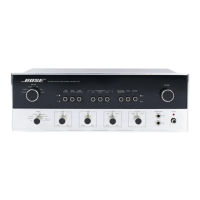
The amplifier responds to the various SmartSpeaker commands issued from the various Bose
Lifestyle
®
head-end units, such as the CD-5, CD-20 and the PMC/MRI used with the Lifestyle
®
40 and 50 systems. The amplifier can also be controlled via an external master remote control
(Philips) used in conjunction with either the CI-1 Control Integrator or the SE-1 Expander.
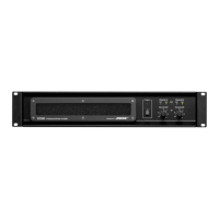
The Digital BUILT-Invisible amplifier is packaged in a metal enclosure, consisting of a steel base
and an aluminum extrusion cover. Internally, the electronics consist of:
- Input/Output (I/O) PCB
- Power Amplifier PCB
- DSP (Digital Signal Processor) PCB
- Toroidal power transformer
Input/Output (I/O) PCB
Note: Unless otherwise noted, refer to the schematic diagram for the Input/Output board for the
following information. The references in brackets [ ] are the grid coordinates for the component.
Analog audio inputs
The audio signals are applied at J6 [A4] and J21 [A3]. J6 is used for Music Audio Inputs and J21
is used for Video Audio Inputs. U1, 2, 7, & 8 [A2-4], dual op amps, comprise the four differential
amplifiers for these inputs. Each differential amplifier uses two op amp sections. The non-invert-
ing (+) input passes through two inverting sections, while the inverting (–) input passes through
only the second inverting section. In this way, the amplifier responds to the difference between
the non-inverting (+) input and the inverting (–) input. External signals appearing in common on
the two input pins (capacitively or inductively coupled noise) are subtracted and are largely
eliminated. To improve common mode rejection, the critical resistances are packaged in a preci-
sion thin film network RN1 [A4] with a high degree of matching. To protect the differential amplifier
against ESD and the presence of higher than normal audio signals with or without power
present, series resistors R105 and R106 [A4] and D25 and D26 [A4] provide clamps. Further
ESD protection comes from the spark gap PCB patterns. C3 and C5 [A4] provide low pass
filtering to remove RF that could be picked up by input wiring.

 Loading...