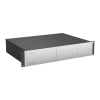
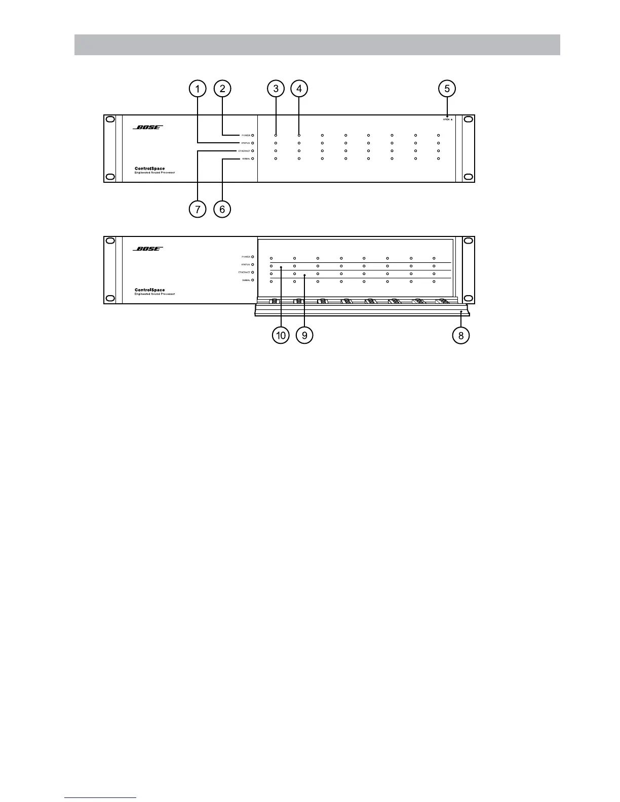
Front Panel Indicators and Features
1. Status indicator
Green = Netlist loaded, operating
Yellow = DSP resource shortage
(delay or cycles)
Red = Errorinnetlist
Off = No netlist loaded
2. Power indicator
Green = Power on
Red = Fatalerror
3. Audio input indicators (4 per audio card slot)
Green= Inputsignal>-36dBu/-60dBFS
Yellow = Inputsignal>=+4dBu/-20dBFS
Red = Clipping,inputsignal>=
+18.0dBu/-6.0dBFS
4. Audio output indicators (4 per audio card slot)
Green= Outputsignal>-36dBu/-60dBFS
Yellow = Outputsignal>=+4dBu/-20dBFS
Red = Clipping,outputsignal>=
+18.0dBu/-6.0dBFS
5. Front door
Shown closed, pull to open
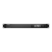
6. Serial indicator
Red = RS232:Rx/Tx
Yellow = RS485:CC-16controller
command received
Green = RS485:CC-16controller
command transmitted
7. Ethernet indicator
Green = Link
Yellow = Tx activity
Red = Rxactivity
8. Front door
Shown open
9. Audio output label area
Apply labels in this area to indicate
the names of the output signals (e.g.
“Center Fill”)
10. Audio input label area
Apply labels in this area to indicate
the names of the output signals (e.g.
“Podium Mic”)
Front Panel