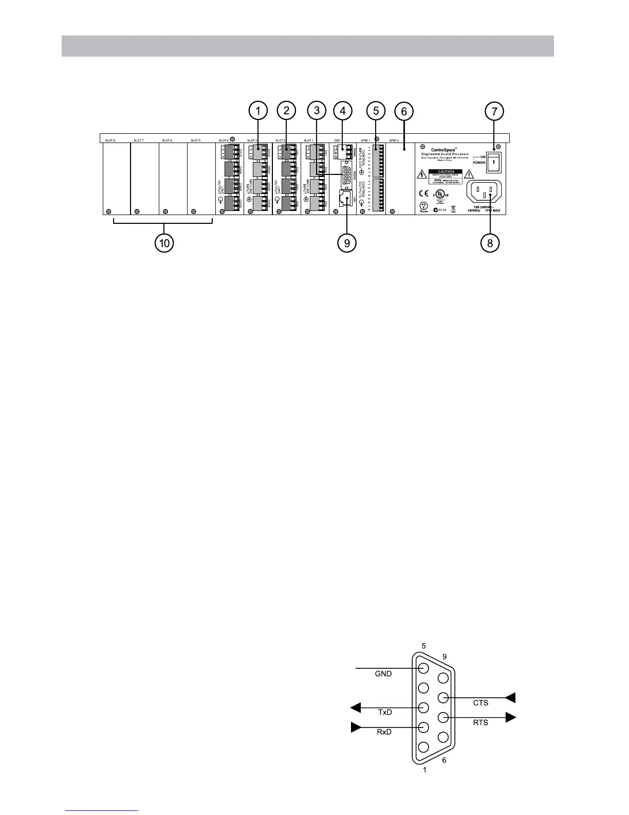
1. Mic/line inputs (ESP-88 only)
Fourbalancedmic/lineinputs(audioinput
connectors are green) in slots 1 and 3.
These are inputs S1-1 through S1-4, and
S3-1 through S3-4 in the ControlSpace
™
Designer software.
2. Line outputs (ESP-88 only)
Four balanced line outputs (audio output
connectors are oran ge) in slots 2 and 4.
These are outputs S2-1 through S2-4
and S4-1 through S4-4 in the Designer
software.
3. RS-232C connector
DB-9 male (DTE)
4. RS-485 connector
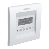
ConnectControlSpaceCC-16
controllers.
5. GPIO card
Eight general purpose control inputs
Eight general purpose control outputs
6. GPIO slot 2
For optional 2nd GPIO card
7. Power switch
ON/OFFACpower
8. AC cord inlet
Connect the AC cord appropriate for your
area.
9. Ethernet LAN connector
Connect to your PC with enclosed cross-
over cable. Or, connect directly to a hub
or router with a straight-through cable.
10. Audio slots 5 - 8
For optional audio cards
RS-232C Serial Port
The ESP features a serial port that can be used to send
to other equipment. The serial port is a DB9 male. The
pin-out is shown in this illustration.
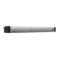
Rear Panel Controls and Connections
Rear Panel
(ESP-88shownESP-00doesnotincludeI/Ocardsandmustbeconguredseparately.)
male
DB9