43
Disassembly Procedures
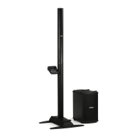
4.4 Remove the screws that secure the bass
module output jack and the ToneMatch jack
to the input / output panel.
4.5 Remove the nuts that secure the analog
input and bass line out jacks to the input /
output panel.
4.6 Remove the Trim knob.
4.7 Remove the six screws that secure the
DSP board to the back of the input / output
panel. Lift out the DSP board.
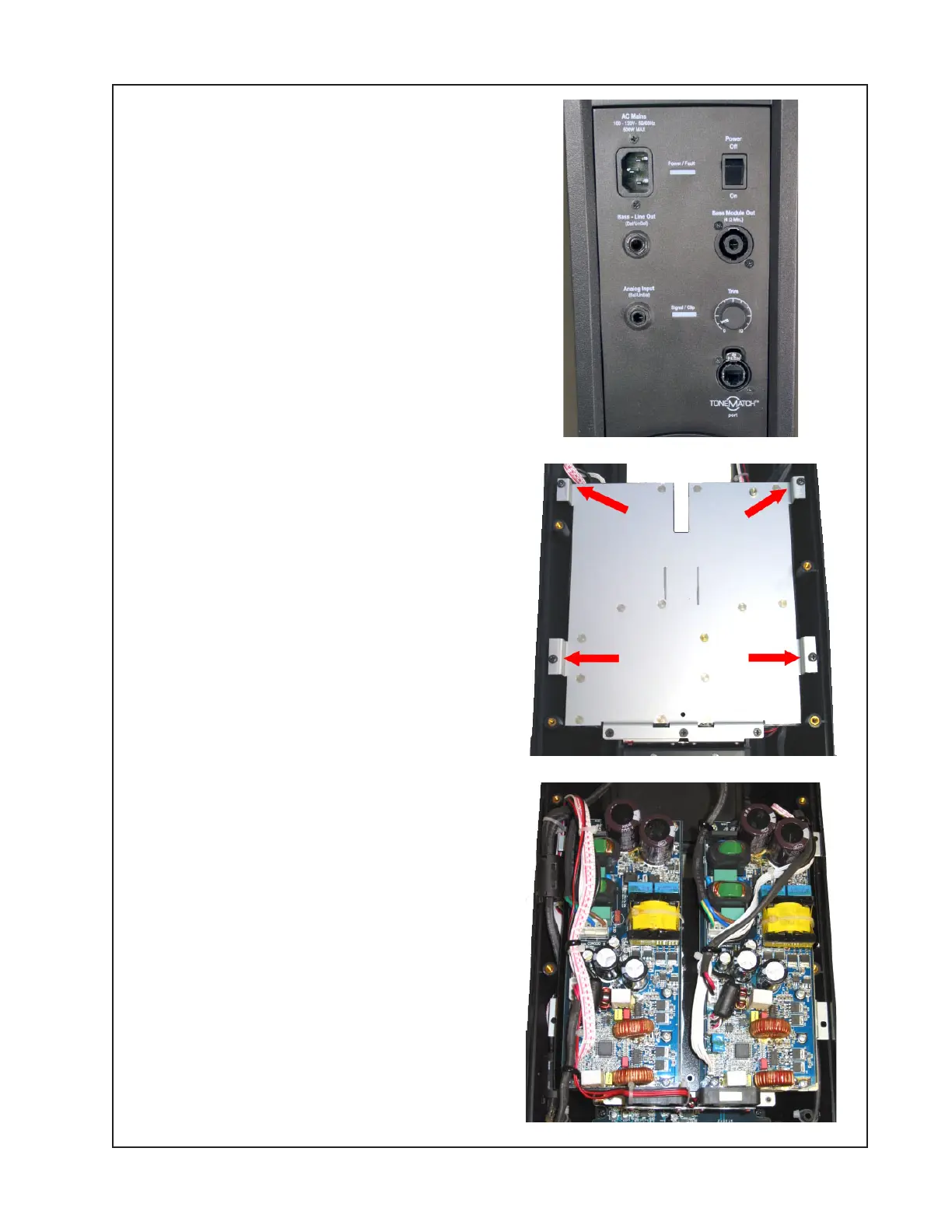
5. Amplifier Board Removal
Note: The amplifier boards used to drive the
line array and bass module are identical.
One amplifier PCB is used for each.
5.1 Perform procedure 1.
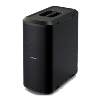
5.2 Remove the four screws that secure the
amplifier PCB bracket to the upper housing.
Do no remove the three screws located near
the power stand handle.
5.3 Flip over the amplifier bracket assembly.
Unplug the wire harnesses at connectors
J301, J302, CON301, J303 and CON300.
5.4 Remove the eight screws that secure the
amplifier PCB assembly to the amplifier
bracket. Lift off the amplifier PCB assembly.
Be sure to retain the thermal pad located
under the amplifier board for re-use.
 Loading...