44
Disassembly Procedures
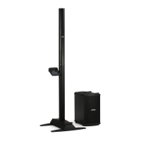
6. Fan Removal
6.1 Perform steps 5.1 and 5.2 above.
6.2 Remove the two screws that secure the
fan. Lift out the fan.
6.3 Unplug the wire harness from CN101 or CN102 located on the DSP PCB.
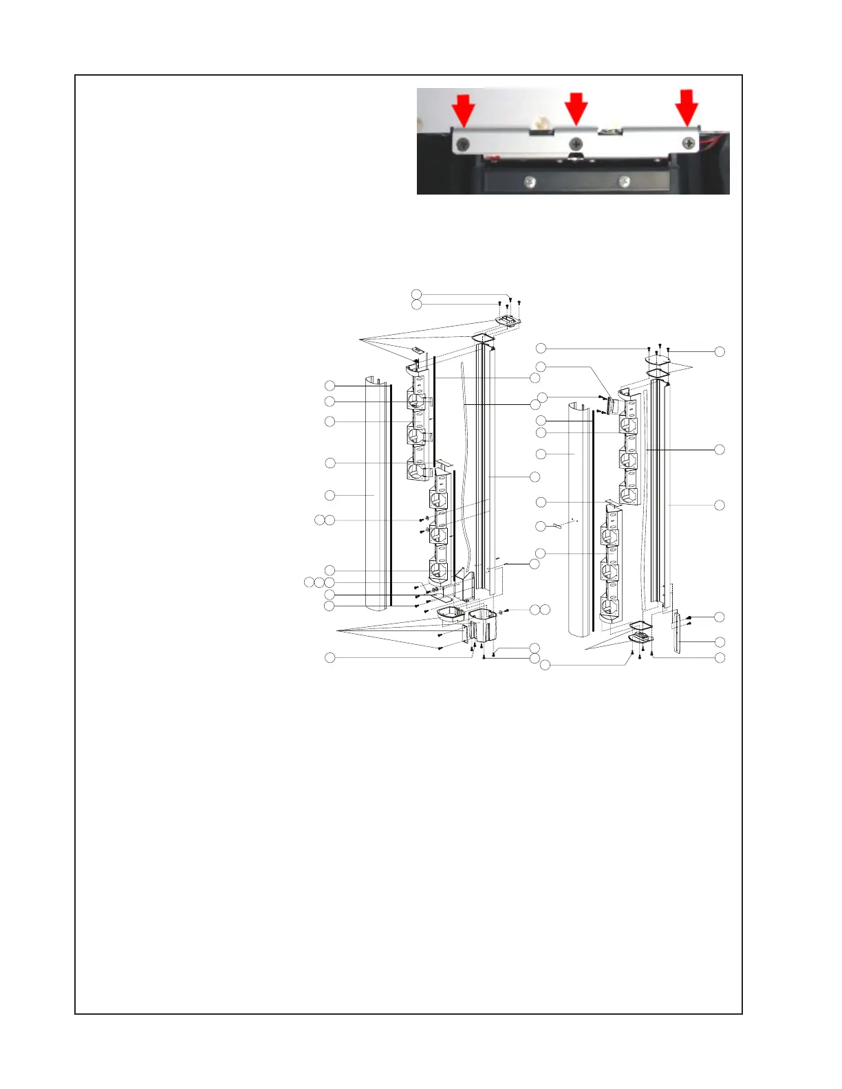
Line Array Procedures
Refer to the figure at right
for the following proce-
dures.
1. Upper Line Array Grille
Removal
1.1 Remove the four
screws (1&2) that secure
the end cap # 1 assembly
to the line array enclosure.
Lift off the end cap. Do not
unplug the molex connector
from the speaker harness.
Re-assembly Note: There
are two different types of
screws used to secure the
end caps to the line arrays.
Be sure to use the correct
screw type in the proper
location during re-assem-
bly.
1.2 Remove the four screws (1&2) that secure the end cap # 2 assembly to the line array enclo-
sure (28). Lift off the end cap. Do not unplug the molex connector from the speaker harness.
1.3 Grasp the edge of the grille (25) and gently lift it away from the enclosure.
2. Bose
®
Logo Removal
2.1 Perform procedure 1.
2.2 On the back of the grille (25), unbend the legs of the logo (26). Lift off the Bose logo.
3. Lower Line Array Grille Removal
3.1 Remove the four screws (1&2) that secure the end cap # 3 assembly to the line array enclo-
sure. Lift off the end cap. Do not unplug the molex connector from the speaker harness. Be sure
to use the correct screw type in the proper location during re-assembly.
LOWER ARRAY
SECTION
UPPER ARRAY
SECTION
END CAP #3
ASSEMBLY
END CAP #4
SSEMBLY
END CAP #2
ASSEMBLY
END CAP #1
ASSEMBLY
1
2
3
4
5
6
7
89
10
11 12 13
14
15
16
2
23
17
24
18
5
25
19
6
26
5
20
21
22
1
2
2
1
30
29
28
27
1
3
 Loading...