53
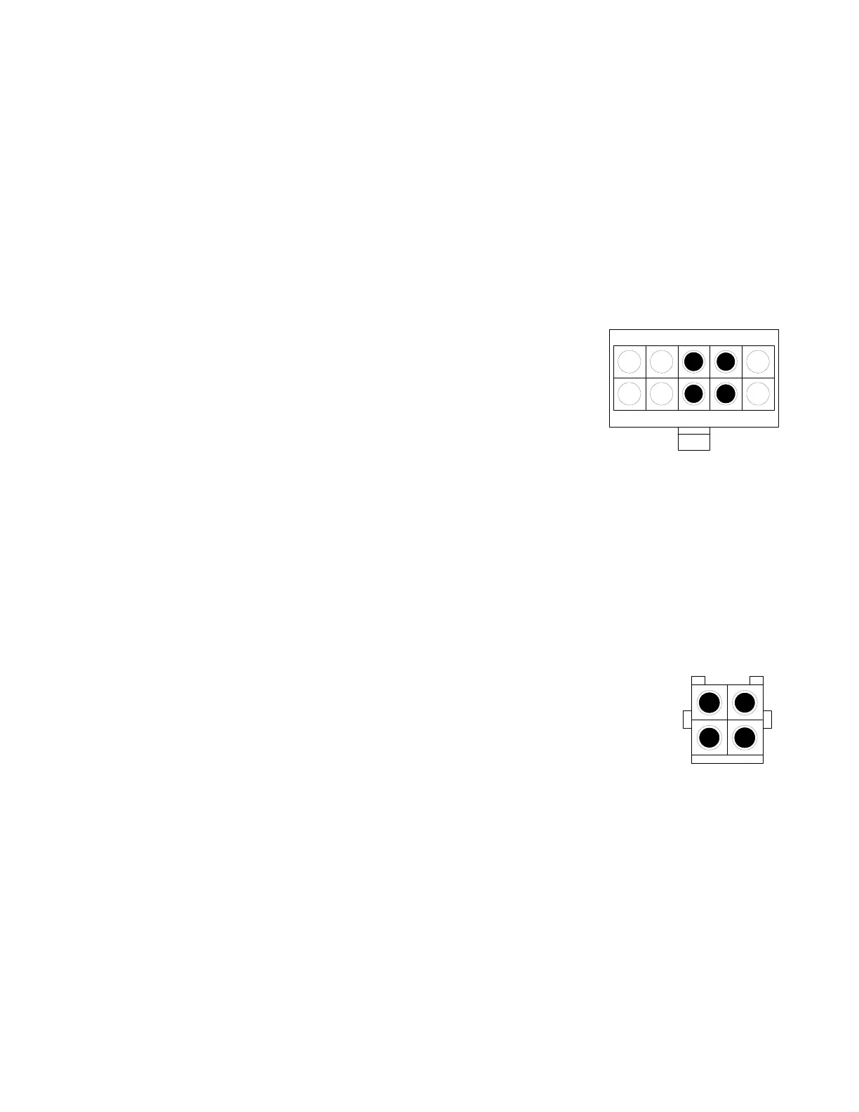
Molex Connector
Rear View
12
34
4. L1
®
Model II Line Array Test Cables
These two cables will allow you to test the upper and lower line array sections without an L1
Model II power stand. Use these cables for the line array test procedures in this service manual.
Lower Line Array Section Test Cable
Parts needed:
1 - 10 pin Molex male connector, Molex part number 39-00-0039 (F)
4 - Molex crimp-on pins for above connector, Molex part number 39-00-0039
1 - dual banana jack
12 feet of 16 or 18AWG twisted pair wire
Cut the 12 foot length of twisted pair wire in half. Strip all of the
wires back about 1/4 inch. Crimp the molex pins onto the wires. The
positive (+) side of the twisted pair wires will go into pins 3 and 8 of
the Molex connector. The negative (-) side of the twisted pair wires
will go into pins 4 and 9 of the Molex connector. Connect the wires
that go to pins 3 and 8 of the Molex connector to the positive (+)
side of the dual banana jack. Connect the wires that go to pins 4
and 9 of the Molex connector to the negative (-) side of the dual
banana jack.
Upper Line Array Section Test Cable
Parts needed:
1 - 4 pin Molex male connector, Molex part number 39-01-2041
4 - Molex crimp-on pins for above connector, Molex part number 39-00-0041 (M)
1 - dual banana jack
12 feet of 16 or 18AWG twisted pair wire
Cut the 12 foot length of twisted pair wire in half. Strip all of the wires back
about 1/4 inch. Crimp the molex pins onto the wires. The positive (+) side of
the twisted pair wires will go into pins 2 and 4 of the Molex connector. The
negative (-) side of the twisted pair wires will go into pins 1 and 3 of the
Molex connector. Connect the wires that go to pins 2 and 4 of the Molex
connector to the positive (+) side of the dual banana jack. Connect the wires
that go to pins 1 and 3 of the Molex connector to the negative (-) side of the
dual banana jack.
Appendix
123 54
678910
Molex Connector Rear View
 Loading...