45
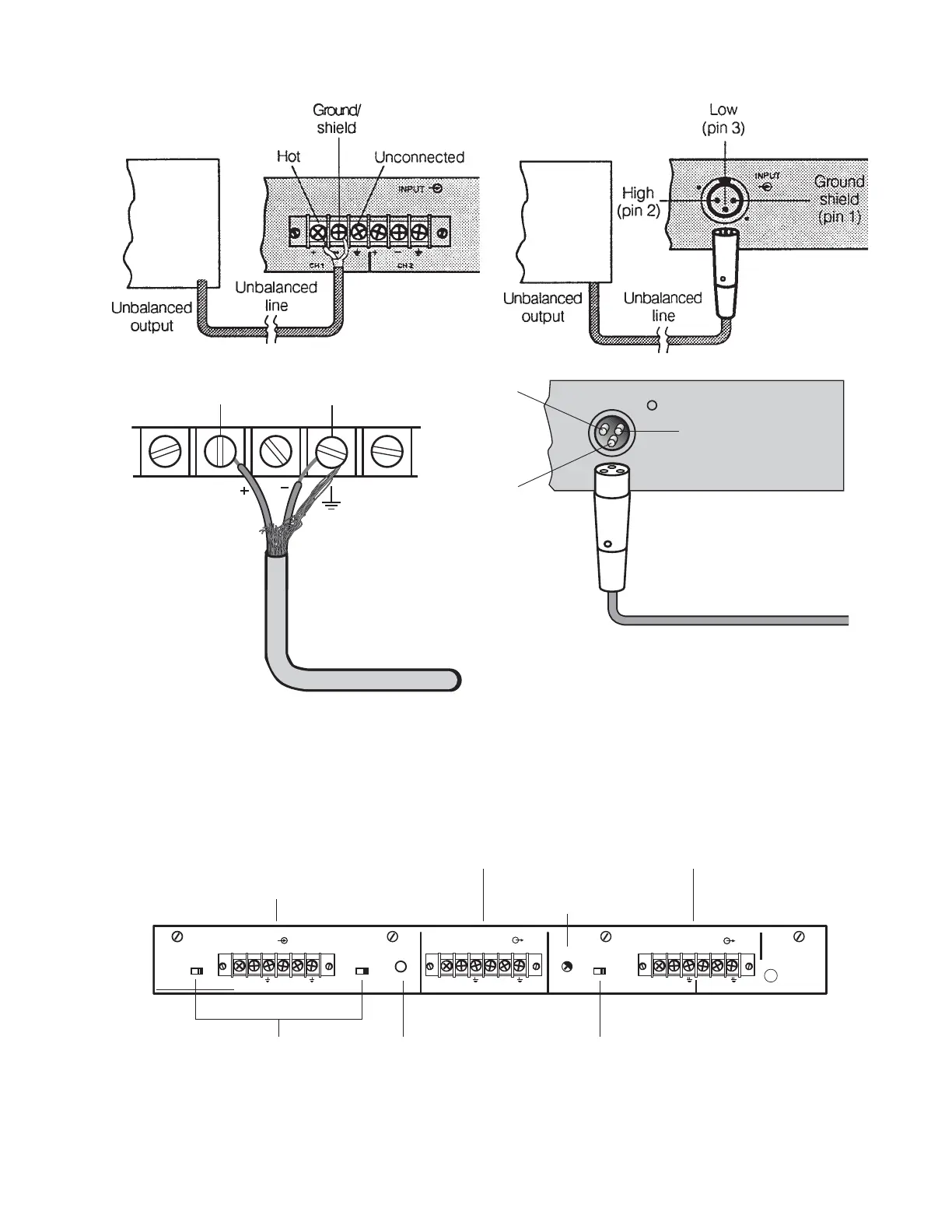
Figure 18. 502C Controller Back Panel (Barrier Strip Version Shown)
Figure 17. Unbalanced Connections
0
.
.
.
.
.
.
.
+3
-18
SER. NO. D.O.M.
CH 1
INPUT LEVEL
–10 +4
INPUT
CH 2
INPUT LEVEL
–10 +4
MODE
4
1
2
3
PROTECTED BY U.S. PATENT 3,038,964
HIGH FREQ OUTPUT
2 HC1 HC
LOW FREQ
LEVEL
BOSE CORPORATION, FRAMINGHAM, MA 01701-9168
ENGINEERED AND MANUFACTURED IN U.S.A.
OUTPUT MODE
NORM SUM
LOW FREQ OUTPUT
CH 1 CH 2
230V
~
AC
50/60Hz 12W
U
L
®
COMMERCIAL
SOUND
EQUIPMENT
LISTED 411F
+– +–+– +–+– +–
Mode
switch
Bass mono
sum switch
Input
attenuator
switches
Input
connectors
Low frequency
output
connectors
High frequency
output
connectors
Bass level
control
Amplifier
Amplifier
Input Connections
Output Connections
OUTPUT
Hot (+)
pin 2
Shield and ground
pin 1
Unconnected
pin 3
To unbalanced input
on amplifier
Hot (+) Shield/ground
To unbalanced input
on amplifier
 Loading...